Team:Grenoble-Alpes/Temperature Control
T°C Control
 It was at Amont à Aussois that we had met that night to sleep by the fireside.
 Credits: Estelle Vincent
How to control the temperature within the kit ?
As biological material is used along the analysis, maintaining a specific temperature within the kit is essential. In order to control the temperature, an electrical circuit was designed using an Arduino card. This system has to first perform an enzymatic cleavage at 37°C .Then, DNA target denaturation at 73°C is realized, and finally, a heat shock occurs which is needed for the bacterial transformation. Whenever the system controlling the temperature must not perform special operations, it keeps the temperature around 37°C.
The idea we had was to design an electronic card with a resistance thermometer which would measure the temperature. With a direct current source, the resistance variation is transformed into a voltage variation. The circuit also required the design of a voltage divider and as well as an instrumentation amplifier to adjust 0V at 0°C. An Arduino card was also essential to compare the tension relative to the current temperature with the tension relative to the temperature wanted. Eventually, the output tension was sent to a power converter, then to the Peltier device to cold or heat within the kit.


Temperature acquisition
The first step was to find a way to detect temperature variations in order to adjust the temperature inside the kit. A specific type of resistance thermometer was used: the Pt100 sensor. In fact, its internal variable resistance changes linearly with the temperature variation. At 0°C, the value of Pt100’s resistance is equal to 100 Ω. But, the problem is that working with resistance variations is not that easy. This is why a continuous current source was added thanks to the LM334 component so as to work with voltage variations.
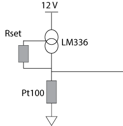
Figure 1: Circuit diagram for the temperature acquisition
The current passing through the Pt100 is set with the LM334, so the resistance variation is converted into a voltage variation. To choose that current, it is recommended to fix it under 1mA, so as to avoid burn it. This is why a resistance Rset was added, which value is given by the following equation.
For a 100 µA current, Rset must be equal to 640 Ω.
Offset regulation
Now, even though the system was designed to have 0°C at 0V, it was not the case, an offset was observed. To compensate this offset, a voltage divider is needed. A reference tension is created, from which the tension related to the temperature is subtracted.

Figure 2: Circuit diagram for the voltage divider performing the offset regulation
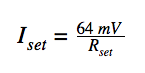
At 0°C, the Pt100 resistance should be equal to 100 Ω and the current which passes through this component is 100µA. Thanks to the Ohm’s relation, the tension can be deduced and it must be equal to 10 mV. The following equation gives the relation between R1 , R2 and VR2.
With two unknown parameters, infinite values of R1 and R2 were possible. We chose R1= 120 MΩ and R2= 100 kΩ, thus VR2 is equal to 9,9 mV.
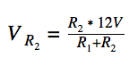
Now, as explained before, the reference tension and the tension related to the actual temperature have to be subtracted. The difference between these two tensions is in the millivolts range which is a little bit too small to be used: the difference was therefore amplified with the AD8223 instrumentation amplifier. This device subtracts the two inputs and amplifies the result by a gain which is defined by the following relation.
where
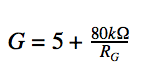
As the Arduino card can’t record tensions higher than 5V, RG was chosen in order to have the output tension included between 0 and 5 V, to use as much as possible the band free tension. As the maximum tension coming from the Pt100 is 12,899 mV (which corresponds to a temperature of 75°C), the resistance fixing the gain can be deduced with the following relations.
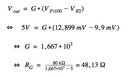
In this way, RG was fixed at 48Ω.
Finally, to protect AD8223 from too high currents, a resistance was added. The Pt100 is a fragile element, so in case it would be disconnected/broke, this new resistance would receive the current from the LM334 instead of going through the AD8223 component and breaking it.
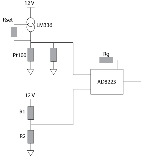
Figure 3: Final circuit diagram for the temperature acquisition
Temperature enslavement
At this point, the AD8223 voltage output was successfully included between 0V and 5V. To enslave the temperature, this output tension had to be compared to a reference voltage, which corresponds to the tension related to the desired temperature.
To do this, the Arduino card was used. As a matter of fact, the Arduino card is able to convert the analogue tension into a numerical tension, between 0 and 1023. Then, with a hardware, this tension can easily be subtracted to the analogue tension related to the wanted temperature which has to be enslaved (its value is fixed by the software). The subtraction result is then amplified. So as to be able to determine the output Arduino tensions, one should explain how the Peltier device works.
A Peltier device is a component which turns current into temperature differences. It can heat or cool according to the sign of this current. Peltier device can be considered as a resistance, so we can consider the tension as the element determining whether the device should heat or cool. However, the output Arduino tension can only be positive, so a power converter needs to be used to make sure it remains positive. Accordingly, a power converter is needed to deliver positive or negative tensions with an input tension that is only positive, because as said before, the output Arduino tension can only be positive. L298 is a power converter and it is the component that we chose.
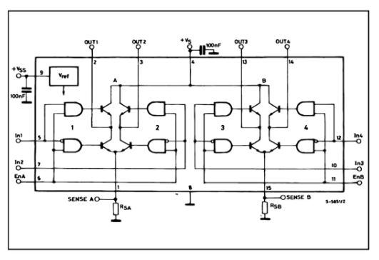
Figure 4: Logical patter of the L298 component, taken from its datasheet
This device has 3 input values : In1, In2 and EnA. EnA is a PWM signal that is needed for the output and In1 and In2 determine the sign of the output signal, whether it is positive or negative. In fact, if In1= Vss and In2=0 V , the output tension will be EnA. On the contrary, if In1=0 V and In2=Vss, the output signal will be -EnA.
Now, in the Arduino card, according to the sign of the difference between the two analogue tensions (the one related to the temperature within the kit and the other related to the wanted temperature), the hardware determines whether the Peltier device has to heat or cool the system. Therefore, it fixes the value of In1 and In2. According to the value of this difference, the hardware generates a PWM sent to EnA. The complete electronic circuit is showed below.
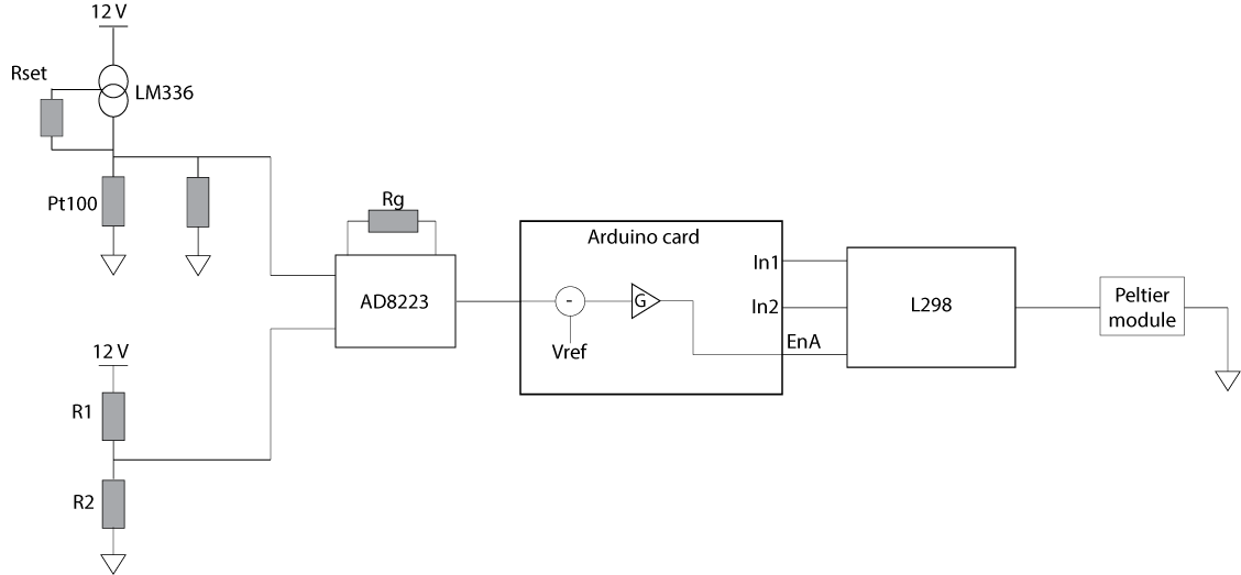
Figure 5: Final global circuit diagram for the temperature enslavement
A SMD card has been realised so further tests could be performed.
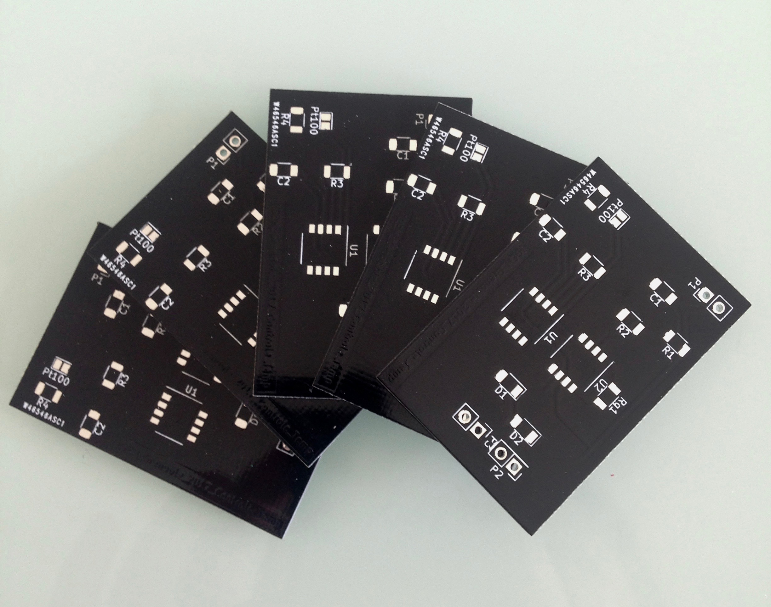
Figure 6: Photo of the SMD cards
Results
To confirm our argumentation, we realised the circuit on an operating console and verified, step by step, that the tensions expected were satisfying. However, due to a lack of time, the SMD card, and so the temperature enslavement, was not tested. The next step would be to test this card, allowing to make further improvements if necessary.