Team:York/Design
The Craic with the QWACC
As explained here, digital inline holographic microscopy uses a set of optical components which are aligned along a single optical axis. With this in mind, along with the familiar design of the average optical microscope, it seemed apparent to us that our microscope should stand upright. This would have benefits including, but not limited to: requiring only a small amount of desktop space and concealing the monochromatic light source (laser) from the line of sight of the microscope's user.
A Defence Against 3D-Printing
The original design for the main body of our Quicker Way to Analyse Co-Cultures (QWACC) revolved around 3D-printing. We wanted to be able to create an open source template for an upright DIHM. However, we soon discovered that there were several problems with this idea.
- Firstly, the most easily accessible 3D-printing materials are prone to warping over time. This would be catastrophic for a microscope whose functionality depends upon the "inline"-ness of its components. In fact, that is one of the defining qualities after which the type of microscope is named.
- Also, the precision of 3D-printing, in the low expenditure range, is limited. This would negatively impact the ability of printed optical component holders to maintain alignment along a single axis. For example, the vertical accuracy of Fusion Deposition Modeling is on the order of millimetres [1]. Any misalignment of this calibre would significantly change the diffraction pattern as seen by the camera [2].
- Finally, while 3D-printing is, often, somewhat quicker than many other methods of construction, there exist at least a few alternatives that are faster still. For example, we used a die-cast box, aluminium profile extrusion, some plastic blocks and several drills and drill bits to form and build the bulk of our microscope. This took, cumulatively, less than a day's worth of work from the moment we had all the raw materials to the time the DIHM was ready for use.
A Whole Lot of Aluminium...
Our final design looked like this:
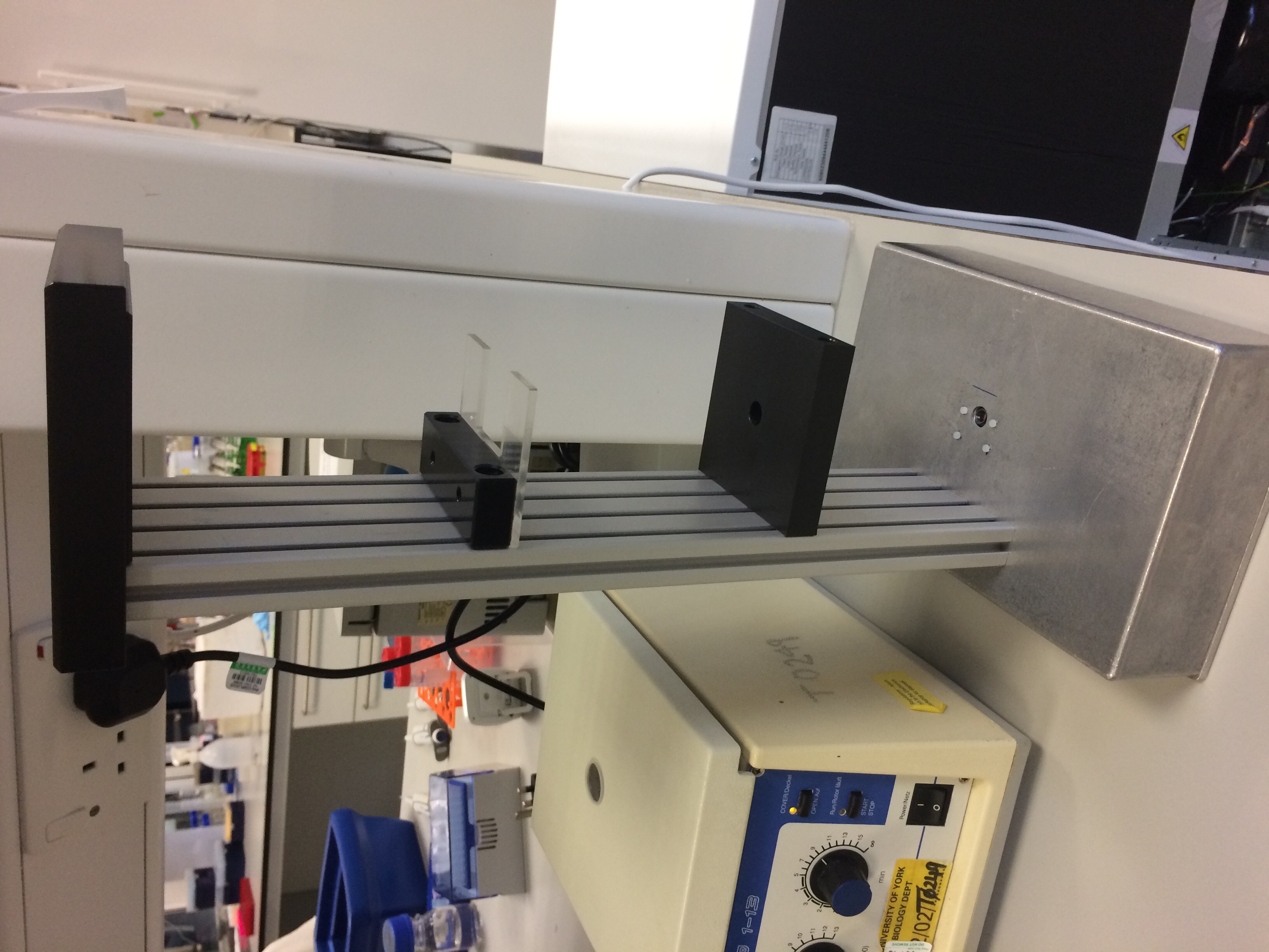
- Figure 1: The completed and assembled DIHM hardware.

This showcases one of the benefits to using aluminium as the basis for the design. Not only is it cheap, easy to acquire and both strong and lightweight, it is also very easy to manipulate and work with. We are a relatively inexperienced team when it comes to making hardware, yet we still found it simple to drill through the base and to prepare the neck for screws without damaging the component pieces.
...and Some Plastic
We had kept in mind that the purpose of this microscope was to analyse co-cultures of microorganisms whose sizes are on the order of microns. The Raspberry Pi Camera Module V2 has square pixels of length 1.12 µm [4]. To be able to see the organisms, they must cover at least a few pixels, meaning that at least some degree of magnification would be required for useful imaging. So, even our preliminary designs included the option to use a magnifying lens.
Since lenses are sensitive to damage, we wanted to avoid optical component holders machined from metal, as they would likely have sharp edges. Instead, we communicated with the Mechanical Workshop in the Department of Biology, University of York, where it was kindly arranged that our optical component platforms (shown below) would be machined from blocks of plastic.
-

- Figure 2: Our DIHM lens platform.
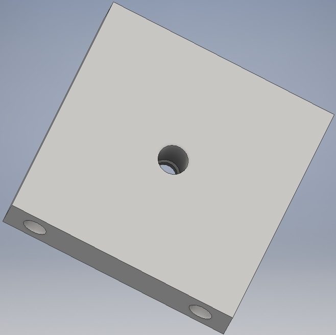
- Figure 3: 3D CAD rendering of our DIHM's lens platform.


Parts of this style are also not susceptible to warping under UV or heat, unlike 3D-printed plastics [5] and, hence, are comparatively durable. We tested the usefulness of the lens platform (along with the laser and slide platforms as seen below) in situ while capturing images of organisms. This was to shorten the time scale of testing and data acquisition. If problems were to arise, we expected that they would be in the alignment of the lens, which would most likely be due to some offset in the positioning of the central hole in the platform - a problem that could be solved through re-making the platform more carefully. As it turns out, this was not necessary.
-

- Figure 4: Platform to hold laser and circuitry.

- Figure 5: Platform to hold slides/milli-fluidic chamber.
- Figure 6: Cover, to conceal circuitry.


Closed Analysis System
Milli-fluidic Analysis Chamber
When designing the closed analysis system outlined on the Description page, we had several considerations to make for the flow chamber itself:
- Channel depth.
- Channel width and roughness.
- Optical flatness.
The channel depth had to be minimised, since the deeper interruption in the path between light source and camera, the more interference appears in the diffraction pattern. We were advised by Dr. Laurence Wilson (who works with biological samples under DIHM) that the upper limit on the depth should be 5 mm. We designed our chambers with depth 3 mm. Due to time constraints, there was no opportunity for us to revise the design of the milli-fluidic chamber after having tested its functionality.
Chlamydomonas reinhardtii, a key part of our project, has a tendency to clump and adhere to surfaces [6]. This is undesirable with respect to the analysis chamber, since clumps of cells in the image are difficult to distinguish from one another and, so, would affect whether it is possible to accurately count the total number of cells in a given volume of sample. In order to avoid this, we considered that the volume of the chamber should be as large as possible, allowing more space for cells to be away from surfaces and edges. This, in theory, reduces the chance of adherence. Limiting the roughness of the chamber also assists to this end. If the inner surfaces were rough, it would be easier for cells to get stuck.
For the same reasons as discussed concerning the vertical accuracy of 3D-printing, above, it was important to maintain flatness of the chamber on the sides facing the laser and camera. To achieve this, we made the decision to use glass slides/cover slips to sandwich a partially complete chamber (one that would otherwise be open at the top and bottom).
-
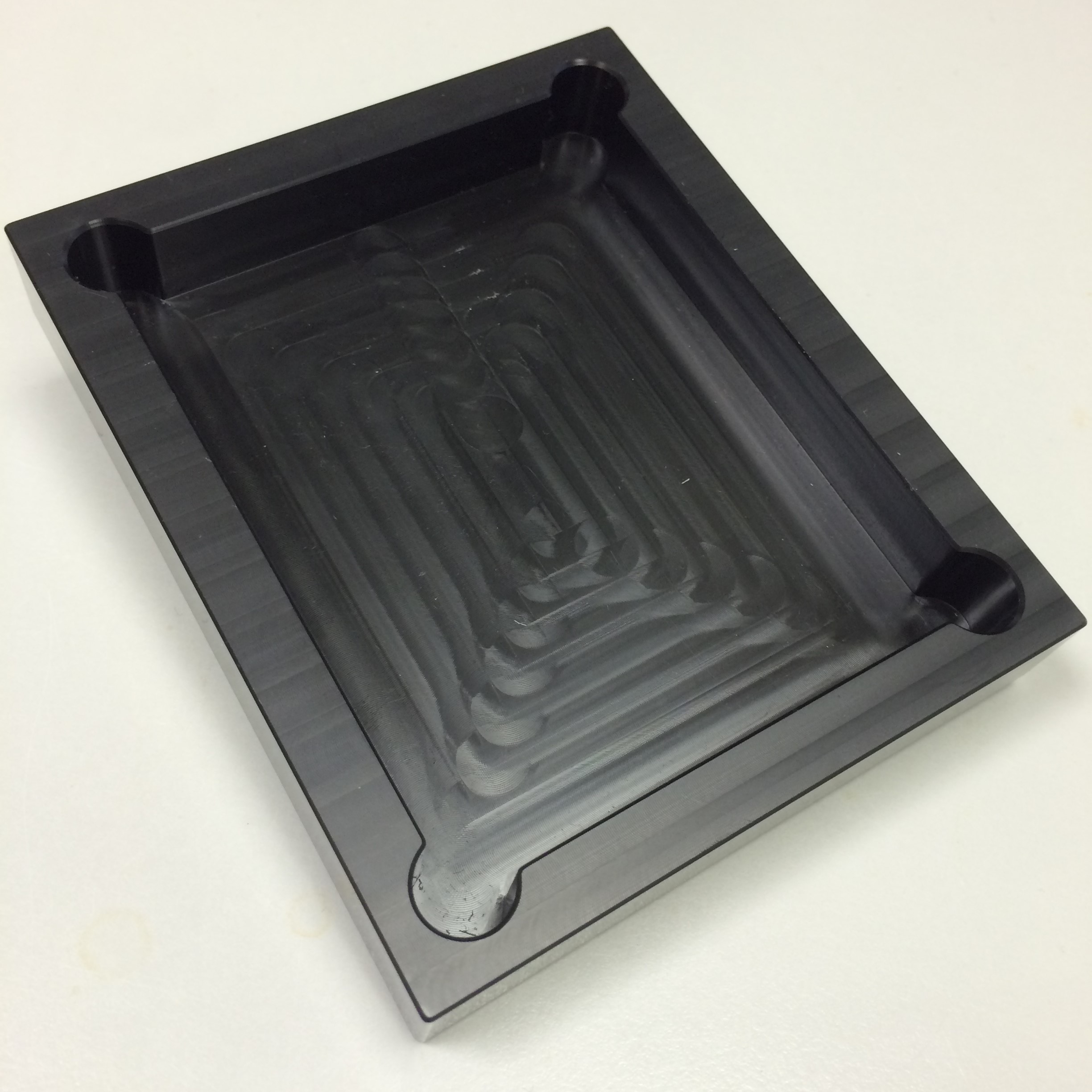
- Figure 7: The PDMS and related chamber iteration.

The first material we considered for the production of mill-fluidic chambers was PDMS - a silicon based polymer which is transparent. This presented itself as a perfect solution. We made a mould for what would be solid cuboids with an indentation in the centre. We then created several of these small pieces of PDMS. It was intended that we would plasma bond a glass slide to the top of each one, creating a sealed chamber on all sides. This did not work, however. The slide did not bond to the PDMS well enough to prevent leaking.
We also tried using super glue to stick the PDMS to a slide, but this often left stains over the field of view and was surprisingly bad at adhering to the glass. Hence, we redesigned our chamber to be manufactured from poly-acryl. This way, the chambers could be redesigned and remanufactured cheaply, easily and with quick turnaround. We discovered that Blu Tack was sufficient for binding the poly-acryl, glass slide and cover slip. Glue was used for cementing the tubes of our peristaltic pump in place in the chamber.
-
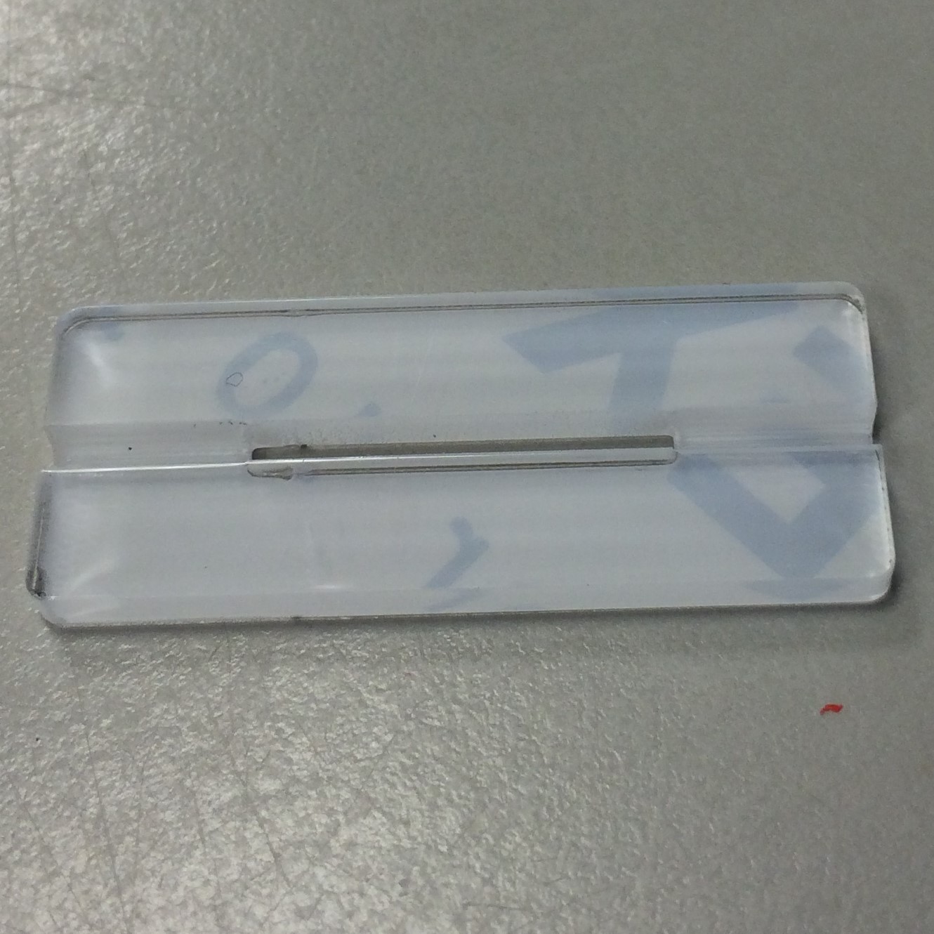
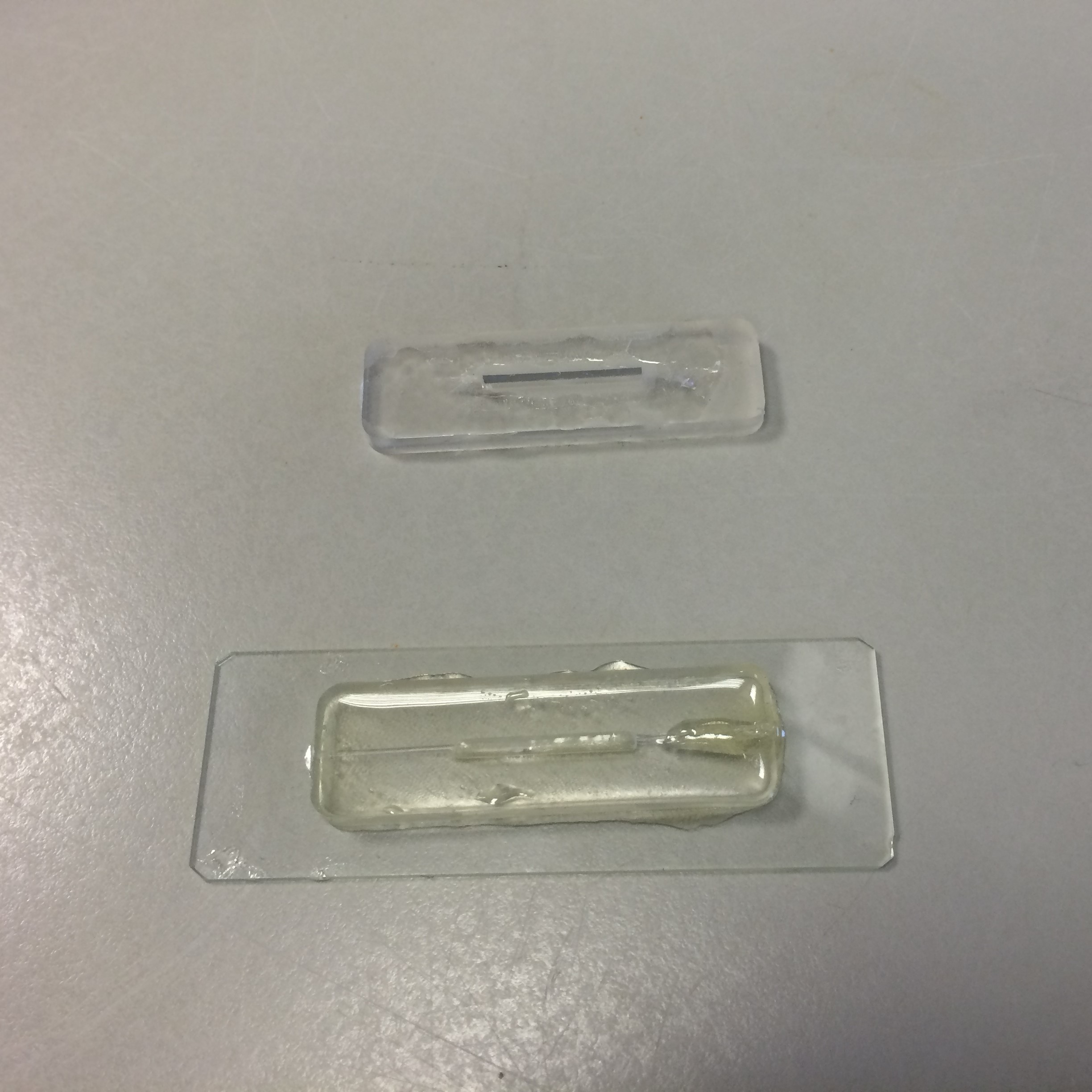
- Figure 8: Poly-acryl piece after manufacture.
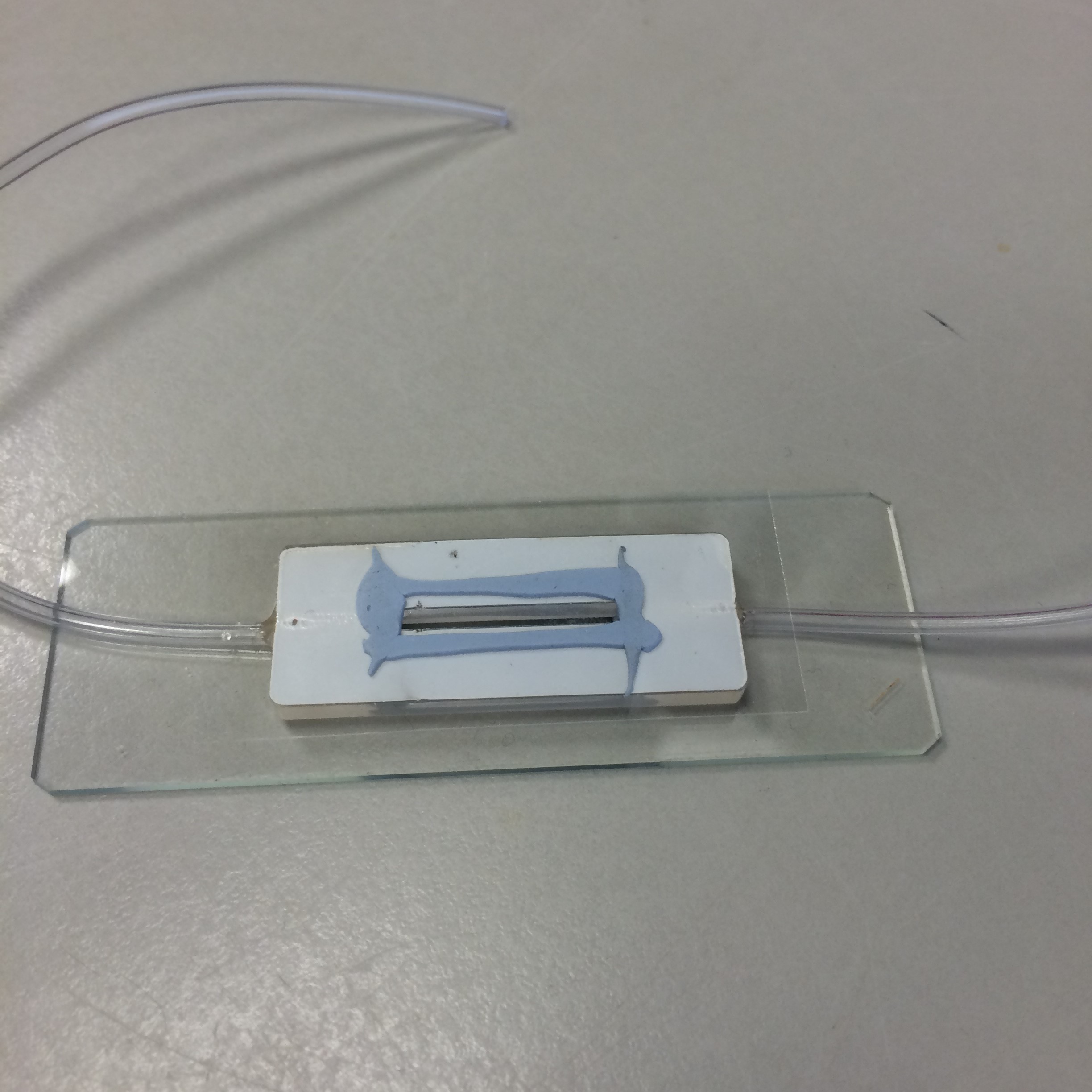
- Figure 9: Poly-acryl chamber, made with Blu Tack.


Peristaltic Pump
We chose to use a 3 V pump with flow rate on the order of millilitres per second. Due to the non-constant peristalsis in the pump and its low flow rate, the movement of pumped fluid is not constant. There are periods during which the liquid is not moving, which is suitable for use in the milli-fluidic chamber, since it reduces the chance that image taking will be impeded by motion blur. We used a peristaltic pump to avoid the maceration, evisceration and/or accidental mechanical lysis of cells.
A Slightly Too Big Problem
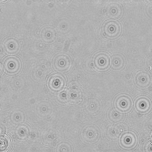
While testing the DIHM, we used the milli-fluidic chamber with C. reinhardtii. We found that we could make out diffraction patterns in the resulting images, but they were extremely noisy. This was due to the depth of the chamber. We are confident that, with a small design change (making the chamber thinner) we could pursue the integration of the chamber into data acquisition properly. We could even preserve the volume by increasing the cross-sectional area. For our results, though, we made use of glass slides. A GIF which serves as an example of the noisiness of our milli-fluidic chamber data is given immediately below. A clump of cells can be seen, though the frames of the clip are dark and "fuzzy".

- Figure 10: A looped clip of our milli-fluidic chamber footage.

Software
Holography
One of our supervisors, Dr. Laurence Wilson, provided us with a sample of code that he wrote in 2012 which takes a foreground and background image of some sample, then mathematically reconstructs the optical field and converts it into a hologram, in the form of a video. With his permission, we used this code to inform the writing of our own reconstruction software, which we have made available under "Digital Inline Holographic Microscopy software (Python)" on the Downloads page. We have written this code so that the output hologram can be produced in video format, or as a series of PNG images, which are the individual frames. Further, as per Dr. Wilson's code, "gradient" videos/frames can also be produced, which depicts the rate of change of pixel values in the hologram. This was useful for us in the detection code, since, in theory, very bright blobs are formed when the focal plane of the hologram meets cells. This, coupled with blob detection in the original hologram was our solution to pin-pointing, and thence counting, cells.
The writing and functionality of the holography software was relatively problem free and no major design changes were required throughout the process.
- Figure 11: Foreground image of C. reinhardtii on glass slide.

- Figure 12: Hologram created from the image in figure 2.
Analysis (Blob Detection & Cell Counting)
We originally intended to use the Hough Transform method to find circles of a given radius in our hologram. Then, using information about the typical size of specific organisms, we could differentiate between different cell types in a co-culture. However, this idea had some fundamental flaws. Firstly, not all microorganisms are circular and, therefore, some do not produce circular diffraction patterns. For us, it was particularly important to note that E. coli are rod shaped. So, we changed our focus to writing blob detection software. This would allow us to detect for different shapes and would still allow us to differentiate by size.
In order to perform the blob detection, we would first need to decide which frame of the hologram was the focal frame, wherein the focal plane of the hologram intersected the cells in the sample. This is not a straightforward task. The frame in which the cells are in focus changes from hologram to hologram and cannot reliably be predicted, due to the statistical nature of the distribution of cells throughout a sample. Hence, we would have had to condense data from the whole hologram into a single image file. We intended to do this by taking the most "in focus" parts of each frame and marking them all on a single PNG. We would do the same for the corresponding bright spots in the gradient. We could run the blob detection algorithm on both images and add the number of detections together (removing one for each time the detections intersected). This would be the best estimate for the number of cells in the hologram's field of view (accounting for doubly-counted blobs).
We had some trouble with this because the foci are not always as clear to a computer as to the human eye. Hence, we used a different approach wherein we reverted to manually choosing the focal frame, this can be found under "Blob Detection (Python)" on the Downloads page.
Control Software
We intended to automate the process of capturing images, analysing and producing cell counts of organisms. To do this, we wrote a user interface (UI) program which would run on a laptop or desktop computer and communicate with the Raspberry Pi in the base of the DIHM via ethernet cable. This can be found under "Microscope Control Application" on the Downloads page. Its primary functions were: instructing the Pi to take images, producing holograms, performing blob detection and displaying the results of the cell counts. Unfortunately, we encountered some resistance when trying to run the software from a laptop. We couldn't take the desktop PC on which the code was developed into the laboratory, so we had to abandon the UI for the testing phase. This was simply due to time constraints with respect to finding a bug fix.
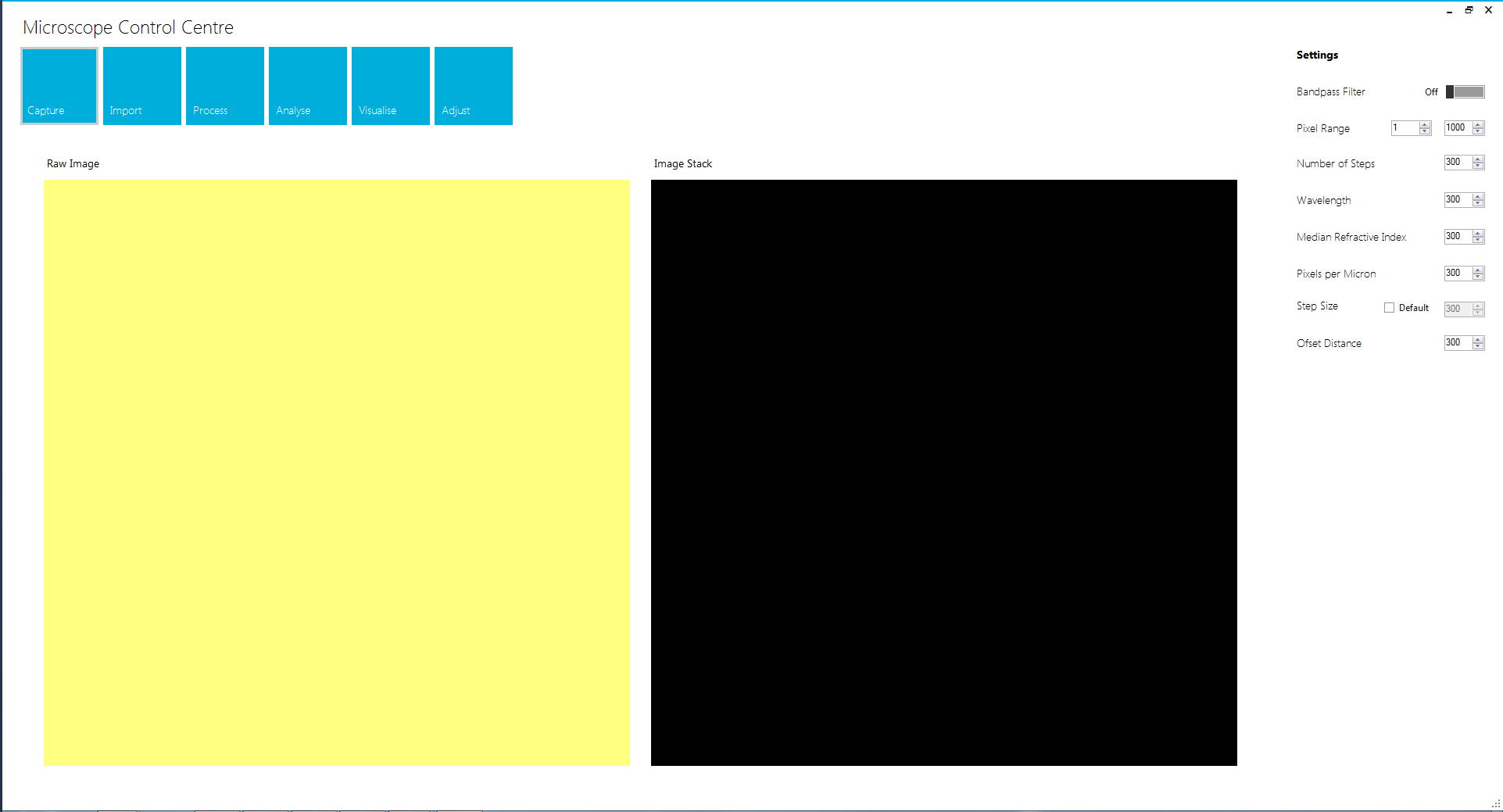
- Figure 13: Our UI program. The bug was an issue with compatibility, this screenshot was taken from the PC on which the code was developed.

Once we realised that we were unlikely to find a bug fix within our time frame, we wrote dedicated software to take series of images using the Raspberry Pi. This can be found under "Taking Series of Images (Python)" on the Downloads page.
Co-culture
As outlined on the Description page, we intended to incorporate a maltose exporter gene into the outer membrane of Chlamydomonas reinhardtii and use it to feed Escherichia coli LW06. We chose these organisms on the basis that both are well understood model organisms. Further, C. reinhardtii can metabolise autotrophically and LW06 produces ethanol, which supports our idea that co-culturing has industrial potential via decreasing the cost of producing biofuels/bioethanol. We made several constructs using ACA-3. We tried one with the whole ACA-3 protein, one with a signal peptide related to the outer membrane and the final one used the signal peptide and first transmembrane domain. We used a backbone containing Venus "YFP" and antibiotic resistance genes so we could later test for the success of transformation. Unfortunately, we later came to see that none of our transformations were successful - nothing grew on our selection plates.
Motility
In order to test the versatility of our DIHM in relation to BioBricks, we used several parts from the 2012 Goettingen team's submission (BBa_K777100 - BBa_K777108). Nominally, these affect the motility of E. coli. We planned to use these to modify E. coli and examine the results under the DIHM. Since it was possible for us to watch the feedback of the camera live, we were able to tell whether organisms were moving or stationary.
References
- [1]: A. Boschetto & L. Bottini (2014), Accuracy prediction in fused deposition modeling, The International Journal of Advanced Manufacturing Technology
- [2]: E. Hecht, Optics (4th Edition), Published 2002
- [3]: item Profile 5, as could be seen on 23rd October 2017 at item-Profile-5-Link
- [4]: Camera Module, Raspberry Pi Hardware Documentation, as on 23rd October 2017 at https://www.raspberrypi.org/documentation/hardware/camera/
- [5]: Xin Li, Zhuo Wang, Jianzhong Shang, Research on the warping deformation in fused deposition modeling, Asian Journal of Research in Chemistry and Pharmaceutical Sciences
- [6]: E. H. Harris, The Chlamydomonas Sourcebook, 2nd Edition.