Difference between revisions of "Team:TAS Taipei/Applied Design"
| Line 225: | Line 225: | ||
</div> | </div> | ||
</div><br> | </div><br> | ||
| − | + | </div> | |
</div><br> | </div><br> | ||
<div class="row"> | <div class="row"> | ||
Revision as of 07:43, 22 October 2017
X

Project

Experiments

Modeling

Prototype

Human Practices

Safety

About Us

Attributions
Project
Experiment
Modeling
Prototype
Human Practice
Biosafety
About Us
Attributions

Prototype
Design, Build, and Test: Putting our project to work
hi
PROTOTYPE
It is estimated that about 95% of nanoparticles used in consumer products end up in wastewater (Kiser et al. 2009). Our goal is to apply our biofilm and Proteorhodopsin (PR) bacteria in wastewater treatment plants (WWTPs) to remove most nanoparticles (NPs) before the effluent is released into the environment.
WASTEWATER TREATMENT
What is the process?

Figure 5-1 Typical wastewater treatment process. Figure: Yvonne W.
When wastewater enters a plant, the first step is to remove coarse solids and large materials using a grit screen (figure 5-1). The water can then be processed in three main stages: Primary, Secondary, and sometimes Tertiary Treatment (Pescod 1992). In Primary Treatment, heavy solids are removed by sedimentation, and floating materials (such as oils) can be taken out by skimming. However, dissolved materials and colloids—small, evenly dispersed solids such as nanoparticles—are not removed here (Pescod 1992). Secondary Treatment generally involves the use of aeration tanks, where aerobic microbes help to break down organic materials. This is also known as the activated sludge process (Davis 2005). In a subsequent sedimentation step, the microbes are removed and the effluent is disinfected (often by chlorine or UV) before it is released into the environment. In certain WWTPs, wastewater may go through Tertiary Treatment, an advanced process typically aimed to remove nitrogen and phosphorous, and assumed to produce an effluent free of viruses. However, Tertiary Treatment requires additional infrastructure that is expensive and complex, limiting its global usage (Pescod 1992; Malik 2014).
Ideally, we would like to remove NPs from all systems, so we visited two different types of WWTPs: a local urban facility in Dihua, Taipei, and a smaller rural facility in Boswell, PA. We found that wastewater is treated using very similar processes in the two plants (figures 5-2 and 5-3). We also contacted Thomas J. Brown, the Water Program Specialist of the Pennsylvania Department of Environmental Protection, and asked him if there were differences between rural and urban plants that we should take into consideration when thinking about implementing our project. He responded, “[t]he heart of the treatment process is the biological process used for treatment; the biology remains the same regardless of facility size.” Thus, in both types of WWTPs, we want to apply our engineered bacteria in the Secondary treatment step—either in aeration tanks or in the sedimentation tank.
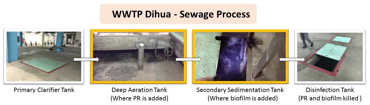
Figure 5-2 Dihua WWTP Sewage Process. Figure: Christine C.

Figure 5-3 Boswell WWTP Sewage Process. Figure: Christine C.
Biosafety
We have chosen to use a safe and common lab strain of E. coli, K-12, as our chassis (Environmental Protection Agency 1977). In both approaches, our constructs do not express proteins associated with virulence: PR is a membrane protein that commonly exists in marine bacteria, and for biofilm production we were careful to avoid known virulence factors such as alpha hemolysins (Fattahi et al. 2015). Most importantly, biosafety is built into WWTPs. Before treated effluent is released back into the environment, it must go through a final disinfection step, where chlorine, ozone, or UV radiation are used to kill microbes still present in the wastewater (Pescod 1992).
PR CONSIDERATIONS AND PROTOTYPE
During our visit to Dihua WWTP, the chief engineer informed us that they use the activated sludge process, which uses aerobic microbes to digest organic matter in aeration tanks. The steady influx and mixing of air provide oxygen favorable to aerobic microbes; the turbulent water can also increase the probability of PR binding to citrate-capped NPs (CC-NPs). Thus, we envision directly adding PR E. coli into existing aeration tanks. In addition, as part of the activated sludge process, WWTPs regularly cycle microbe-rich sludge back into aeration tanks to maintain the microbial populations (figure 5-1). Ideally, this would stabilize the PR bacterial population in aeration tanks, allowing this system to be low-maintenance and easily adaptable to existing infrastructure.
BIOFILM CONSIDERATIONS
To achieve our goal of applying biofilms in WWTPs, we need to inform WWTP managers on the amount of biofilm necessary to trap their desired amount of NPs. Thus, we devised two experiments to investigate the effect of 1) biofilm volume and 2) biofilm surface area on NP trapping; the results of these experiments were incorporated into our model. (Learn more about modeling here!)
Volume Does Not Affect NP Trapping
To test the effects of biofilm volume, E. coli biofilms were grown, extracted, and washed as described in the Experimental page. These tests were performed with AuNP. Because AuNP solution is purple in color, we could take absorbance measurements and convert these values to AuNP concentration using a standard curve (figure 5-4A). 10 mL of Gold NP (AuNP) solution was added to different volumes of biofilm (figure 5-4B). The containers were shaken at 100 rpm overnight to maximize interaction between the biofilm and AuNPs. Finally, the mixtures were transferred to conical tubes and centrifuged to isolate the supernatant, which contains free AuNPs quantifiable using a spectrophotometer set at 527 nm.
Adding more than 1 mL of biofilm to the same amount of AuNP solution did not trap more AuNPs (figure 5-4C). We observed that 1 mL of biofilm was just enough to fully cover the bottom of the container. Since only the top of the biofilm directly contacted the AuNP solution, increasing biofilm volume beyond 1 mL simply increased the depth and not the contact area between biofilm and AuNPs. We concluded that biofilm volume is not a main factor determining NP removal.

Figure 5-4 Biofilm volume does not affect NP trapping. A) AuNP standard curve relates absorbance and molar concentration. B) Different amounts of biofilm were added to same amount of AuNP solution. C) Increasing biofilm volume beyond 1 mL does not increase NP removal. Experiment: Yvonne W.
Surface Area Affects NP Trapping
Next, we tested the effects of surface area on NP removal. Similar to the previous experiment, biofilms were extracted and washed. Two experimental groups were set up in different sized cylinders, with either a small (~1.5 cm
2 ) or big (~9 cm
2 ) base area (figure 5-5A). The bottom 0.5 cm of each container was covered by biofilm, then 10 mL of AuNP solution was added. In this case, the depth of biofilm is consistent, and the contact area between AuNPs and biofilm is equal to the area of the container’s base. All containers were shaken at 100 rpm at room temperature. Every hour (for a total of five hours), one replicate from each group was centrifuged and the absorbance of free AuNPs in the supernatant was measured at 527 nm.

Figure 5-5 Increasing NP-biofilm contact area increases NP removal. A) Different sized cylinders were used to change NP-biofilm contact area. B) AuNPs were trapped much faster in the large container with a greater biofilm surface area. Experiment: Justin P., Florence L., Yvonne W.
We observed that AuNPs were trapped much faster in the large container with a greater biofilm surface area (figure 5-5B). Using data from this experiment, our modeling team computed the concentration of NPs trapped per unit surface area, a constant which was integrated into their model. (Learn more about it here!)
BIOFILM PROTOTYPE
Our goal is to design a prototype that 1) maximizes the contact area between biofilm and NPs, and 2) can be easily implemented in existing WWTP infrastructure.
Maximize NP-Biofilm Contact Area
Some aquariums already utilize biofilms grown on plastic structures called biocarriers for water purification. Commercial biocarriers use various ridges, blades, and hollow structures to maximize surface area available for biofilm attachment (figure 5-6A). With that in mind, we designed and 3D-printed plastic (polylactic acid, or PLA) prototypes with many radiating blades to maximize the area available for biofilm attachment (figure 5-6B). We used PLA because it was readily available for printing and easy to work with, allowing us to quickly transition from constructing to testing our prototype.

Figure 5-6 Biocarriers enable biofilm attachment. A) An example of commercial biocarriers. B) We 3D-printed our prototype to maximize surface area for biofilm attachment. C) We observed biofilms loosely attached onto our prototype. Prototype: Candice L., Yvonne W. Experiment: Yvonne W.
To test how well biofilms actually adhere and develop on our prototypes, we used BBa_K2229300 liquid cultures, since they produced the most biofilm in previous tests. After an incubation period, we observed biofilm growth and attachment to our prototypes (figure 5-6C). However, when we lifted the prototype, most of the biofilm fell off, showing that it was only weakly attached to our prototype. We next tested different types of plastic, including polystyrene, but found that our biofilms adhered much better to glass surfaces (i.e. glass coverslips) compared to plastic (figure 5-7). To improve adhesion in the future, we would try to use glass as the material, or change our chassis from E. coli K-12 to another bacterial strain that shows better attachment to plastic surfaces.
