

Overview
Purification Column EluX
To verify the elution as easily as possible, we created a fusion protein containing GFP for a visible fluorescence signal and streptavidin to immobilize the protein in our column using biotin. The two protein parts are connected through a flexible glycine-glycine-serine-linker of eleven amino acids, in which the sixth amino acid is our 2-NPA. This ncAA will then induce the cleavage of our target protein (GFP) from the streptavidin compound in the purification process.
Design & Development
Purification Column EluX

Figure 1: The six steps in the development process of the purification column
A) BSA-coated micro well plate, B) Hollow cylindrical column, C) Biotinylated microscope slides, D) First flow model, E) second flow model, F) future concept of a microfluidic like column.
BSA-coated micro well plate

Figure 2: Concept of a microwell plate coated with biotinylated BSA.
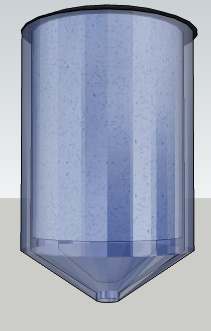
Cylindrical column

Figure 3: Concept of our cylindrical column
3D-Modell of a hollow column with an LED-rod in the middle and a carrier material coated with biotinylated BSA as first concept of a purification system using 2-NPA.
Biotinylated glass slide

Figure 4: Three microscope glass slides as basis for biotinylated surfaces for the purification column.
First flow model

Figure 5: EluX prototype one.
First flow model of a purification column with parallel biotinylated glass slides inside and UV-permeable acrylic glass plates in front and back to enable the radiation with light of 365 nm wave length.
Second flow model

Figure 6: EluX prototype two.
Second flow model of a purification column as basis for a workshop and a 3D-printed model to test, evaluate and improve the concept of light induced elution.
Future microfluidic / flow-bundle model

Figure 7: Future concept of EluX.
Concept of a microfluidic like (a) and a bundle (b) purification column designed with the support of Dr. Benjamin Müller and Prof. Dr. Dirk Lütkemeyer as future prediction of how the procedure of light induced elution could be used.
Construction
Purification column EluX
3D-Printed show model

Figure 8: 3D-printed parts of the purification column.

Figure 9: Preparation of the non-3D-printed parts at the home of team member Markus.

Figure 10: Inside and outside of the EluX prototype.

Figure 11: Comparison of the build and presented show model and the 3D-Model.
Theoretical basics
Affinity Purification columns

Figure 12: Workflow of the common procedure of an affinity purification process.
Biotinylation of silicon

Figure 13: Hydroxylation of a silicon surface with piranha acid and treatment with APTES do get free amine-residues on the surface, followed by biotinylation with NHS-biotin.
References
Acres, R. G., Ellis, A. V., Alvino, J., Lenahan, C. E., Khodakov, D. A., Metha, G. F., & Andersson, G. G. (2012). Molecular structure of 3-aminopropyltriethoxysilane layers formed on silanol-terminated silicon surfaces. Journal of Physical Chemistry. 116(10): 6289–6297.
Lapin, N. A., & Chabal, Y. J. (2009). Infrared characterization of biotinylated silicon oxide surfaces, surface stability, and specific attachment of streptavidin. Journal of Physical Chemistry. 113(25): 8776–8783.


