Team:Bielefeld-CeBiTec/Hardware

Hardware

Short Summary

LED panel

We designed and constructed a multifunctional LED panel in a 96-well microtiter plate format through multiple rounds of optimization. This device enables the sophisticated irradiation of samples with a high resolution of light of different wavelengths and intensities. Using our self-written Android application, complex illumination protocols can be programmed and send to the device via bluetooth. We demonstrated and evaluated the functionality by exciting and bleaching GFP and inducing conformational and structural changes of non-canonical amino acids by irradiation at 367 nm and 465 nm. After initial testing, the panel was applied for various crucial experiments. Full documentation and utilization of low cost components enable easy rebuilding, customization and application by other teams. We envision several applications like mutagenesis, surface decontamination, fluorescence studies, opto-genetics, opto-proteomics and photo-biochemistry.

Purification Column EluX

One of the non-canonical amino acids (ncAAs) we decided to integrate into our toolkit is 2-nitro-phenylalanine (2-NPA). This ncAA is very interesting to us, as it could induce a cleavage of the peptide backbone when radiated with light of ʎ = 365 nm wave length. This promises a wide field of possible applications. To demonstrate this astonishing feature, we use this ncAA to introduce a protein purification system with light-induced elution as an alternative to protease cleavage sides. To put this idea in practice, we started the modelling of a purification column in SketchUp and constructed it with 3D-printed parts and acrylic glass. In this development process, we integrated many advices from professors and experts to render the model as efficiently as possible.
To verify the elution as easily as possible, we created a fusion protein (BBa_K2201321) containing GFP for a visible fluorescence signal and streptavidin to immobilize the protein in our column using biotin. The two protein parts are connected through a flexible glycine-glycine-serine-linker of eleven amino acids, in which the sixth amino acid is our 2-NPA. This ncAA will then induce the cleavage of our target protein (GFP) from the streptavidin compound in the purification process.

LED panel: Overview

Background

Nowadays, light induced reactions are omnipresent both in microbiological as well as chemical experiments. As examples, fluorescent proteins and chemicals must be excited at certain wavelengths in order to detect their emittance and ultraviolet (UV) light can be used to introduce mutations in in vivo experiments.
Regarding our project, two of the ncAAs that are part of our toolbox perform an autocatalytic reaction upon irradiation with ultraviolet light. Therefore, we decided to build our own hardware that allows us to perform experiments with these non‑canonical amino acids under reproducible irradiation conditions.

Design Criteria

We aimed to develop a device which is not designed for our applications exclusively, but rather adaptable to a broad variety of experiments. Therefore, we quickly decided to build a device which is optimized for the illumination of a 96‑well microtiter plate, the most central part of modular, standardized molecular biology. As a starting point for the design process we created a list of criteria that we wanted to be fulfilled:

  • Multifunctionality
    The device should be modifiable to emit light of different wavelengths, ensuring that it is applicable for many different purposes.
  • Modularity & Compact Size
    It should be compatible with other instruments processing microtiter plates.
    Therefore, the outer dimensions of the device shall not exceed those of commonly used microtiter plates.
  • Narrow Irradiation Spectrum
    A narrow distribution in the irradiation spectrum around the desired wavelength is preferred to prevent the occurrence of unintended reactions. This is especially important concerning highly energized ultraviolet light that could lead to protein degradation.
    Regarding this criterion, light emitting diodes (LEDs) are the best choice as the source of light. They are small, have a good energy conversion efficiency and emit light in a very narrow distribution around their irradiation maximum.
  • Illumination Uniformity
    To ensure reproducibility of the experiments and comparability between different wells of the microtiter plate, a uniform illumination of all wells is essential.
    Our approach is to provide an individual LED for every single well of the microtiter plate, providing equal conditions in all wells. In contrast, a single source of light creates a cone of light with decreasing intensities towards the outer regions. Additionally, individual LEDs allow for a more compact size and a higher operation flexibility.
  • Intuitive & Flexible Operation
    The operation of the device should be intuitive while offering the possibility for advanced settings such as time and position dependent variations in illumination strength.
    Therefore, we decided on two possible interfacing options: A convenient operation via a single turning knob and an LCD display which is suitable for simple applications. For more complex tasks, the device can be operated via Bluetooth by a self‑programmed application for android.
  • Accessibility
    To enable other iGEM teams to use this hardware tool for their experiments, all schematics and designs of the device need to be accessible and its construction feasible. Additionally, the software used in this project needs to be available and easily comprehensible.
    We proudly provide everything you need to build your own LED panel, including detailed instructions and commented software. This way, the whole LED Panel can be adjusted to perfectly fit the individual requirements of your experiments!
  • Safety
    The device can be fitted with ultraviolet LEDs which are harmful but invisible to the human eyes. Therefore, the operator must be warned by an indication light showing that the LEDs are operational.
    While the simplest option is a software controlled statues LED, we decided on a hardware solution which is failsafe even in case of a malfunctioning software.

LED panel: Development

Prototyping

As none of our team members is trained in electro mechanics or had any experience with designing circuit diagrams and circuit board layouts, we had to learn everything in the process. Beginning with basics in electronics over advanced circuit design to programming microcontrollers, the process of creating this hardware tool held many exciting challenges that needed to be faced.
In the process of developing our LED panel, we designed, tested and evaluated several different prototypes until we came up with our final version. In accordance with the most central concept of engineering, our design was enhanced by every cycle of this “design ‑ build ‑ test" loop.
A demonstrative example of this evolutionary approach is the development of the interfacing options to control the LED panel. At the beginning, we had only one central conceptual idea: We wanted to create a device that uses 96 LEDs to uniformly illuminate an entire microtiter plate.

Different through‑hole LEDs.

Due to their convenient handling, our first idea was to simply use standard through‑hole connected LEDs and control them with a simple on‑off switch. A first test circuit on a breadboard was quickly build, but this design turned out to have several disadvantages. First of all, the construction process is quite circumstantial, because every LED needs to be positioned and soldered by hand, inevitably resulting in inaccuracies which lead to an unequal illumination profile. More importantly, this approach lacks the flexibility that we wanted to achieve, since neither the illumination intensity nor its duration are precisely adjustable. Every LED requires a predefined series resistance, that needs to be newly calculated for every new kind of LED that should be used, leading to extensive work when adopting the device for a new purpose.
Therefore, we decided that a microcontroller is necessary to provide a basis for increased functionality. A microcontroller has a reprogrammable processing unit and offers several general‑purpose input/output (GPIO) pins to control and communicate with other microelectronic components in a circuit design. Our first choice was an Arduino Nano, as it is the most commonly used microcontroller with small dimensions and a convenient programming interface while being comparably inexpensive. The first prototype with an Arduino Nano used serial‑in parallel‑out shift registers to control the LEDs. These electric components convert a digital signal (a series of ones and zeros) into a parallel output. Therefore, they allow to control multiple LEDs with only one digital output pin. This way, this prototype was able to control all 96 LEDs individually, even though the Arduino Nano only has 22 GPIO pins. Nevertheless, the LEDs can only be turned on and off.
The next major improvement was the decision to use a pulse wave modulation (PWM) controller for the LEDs. A PWM controller has multiple output connections through which it controls connected LEDs individually. In addition to the aforementioned methods, the mean intensity of each LED can be adjusted as well. In principle, these kind of controllers have an integrated circuit (IC) with a storage unit that caches information about the brightness of every connected LED. This storage can be addressed by the microcontroller via a communication protocol similar to the popular Serial Peripheral Interface (SPI) protocol: A single data bus is used for transmitting digital data to every connected peripheral device, while a second, individual connection is used to determine which device shall be listening. This way, in order to control a number of n peripheral PWM controllers only n+1 GPIO pins are needed. In our case, we decided on the TLC5947 from Texas Instruments, a constant current 24‑channel PWM controller that operates on our supply voltage of 5 V. We therefore need four of these controllers for our 96‑LEDs.

The TLC5947 PWM controller on an adafruit breakout board.

With the increased potential of having a microcontroller and the possibility to adjust the LED's brightness, a simple on‑off button is insufficient. Therefore, we evaluated different interfacing options. The first and easiest option we tested is a series of status LEDs, each indicating a different intensity setting. A single button could be used both for switching between the different settings, and for turning the LEDs on or off by differentiating between pushing the button for a long or a short period of time. Unfortunately, the microcontroller has to be reprogrammed every time that a different set of illumination settings is needed. More importantly, the illumination time cannot be set precisely. In order to be able to adjust the time and intensity precisely, a display is necessary.

Two 7‑segment displays connected via two 8 bit shift registers.

One possibility we evaluated is to use a series of 7‑segment displays. A 7‑segment display basically consists of 7 LEDs that are arranged in shape of an 8, so that any digit between 0 and 9 is displayable. An additional 8th LED serves as a decimal point. Our prototype with two of these 7‑segment displays controlled by the Arduino Nano via two 8 bit shift registers worked perfectly. By pressing a button, the displays switches between showing either the illumination time in a range from 1 second to 60 minutes, or the LED's intensity in percent. The only problem with this interfacing option is the amount of wires needed for its connection. As the displays need to be attached to the outer side of the case protecting the circuitry and the operator, all connections would have to be made using isolated cables. This is disadvantageous in terms of assembly, heat dissipation and durability.
The next evolutionary step was to use a LCD‑display as the central user interface. The model that we decided on is a 128 x 64 pixel LCD‑display that is controlled via the Inter‑Integrated Circuit (I2C) protocol. This protocol uses two bidirectional open-drain lines, the Serial Data Line (SDA) and the Serial Clock Line (SCL). Both are pulled‑up to V+ with resistors. In principal, digital data is transmitted over SDA by pulling the voltage down to ground, synchronized with a regularly switching voltage of SDA that specifies the frequency of the data transmittance. The peripheral device called "slave", in this case our LCD‑display, is addressed by its individual 7‑bit address.
The LCD‑display offers a greatly enhanced flexibility and even allows to display images in low resolution, for example our team logo. To make use of these enhanced capabilities, we decided to leave behind the control buttons and tried something more intuitive: A rotary encoder. A rotary encoder is basically a turning knob that has no scaling and is endlessly rotatable both in clockwise and anticlockwise direction. It emits a distinctive signal to the microcontroller when rotated into either of the two directions. Because it has no scaling, the microcontroller program has to interpret these signals and display the corresponding action on the LCD‑display. Even though this requires a more complex software, the amount of cables needed is greatly reduced. In addition, the turning knob of the rotary encoder encloses a button as well. By pressing the turning knob for a short period of time, we programmed the microcontroller to switch between adjusting the illumination intensity or duration when the rotary encoder is turned. By pressing and holding the turning knob, the illumination is started.

A rotary encoder and the I2C controlled LCD‑display showing our team logo.

This interfacing option turned out to be perfectly suited for our application. Furthermore, it is easily adoptable when additional features need to be added in future. No hardware modifications are needed, because both the display and the rotary encoder are controlled software sided. With this important criteria in mind, we even went a step further and added Bluetooth to our LED device!

HC05 Bluetooth dongle that receives a series of advanced illumination settings from our android application.

While the rotary encoder in combination with the display is perfectly suited for simple applications, where constant illumination is sufficient, we wanted to enable others to use the LED panel in a more complex environment. For example if the LED panel is used inside another hardware device, where the manual controls are not accessible, or if advanced illumination settings such as time‑dependent variations in illumination intensity is needed. For these cases, we included the Bluetooth dongle HC05 into our prototype and wrote our own powerful and versatile Android application to control the LED panel. The app allows users to create a sequence of illumination settings, reaching from constant illumination intensity over linear, exponential or logarithmic changes of intensity over time, to gradient settings.
Through this repeating process of planning, constructing and testing different prototypes, we are proud to came up with a solution that is both user-friendly and versatile at the same time. The combination of a rotary encoder and a Bluetooth application ensures that our hardware device is prepared for every application, no matter how challenging it is. Based on the results from this prototyping phase, we began developing a circuit diagram and designing a printed circuit board (PCB) for mounting the components of our final hardware product.

PCB Design & Circuit Diagram

After our extensive prototyping, the next step in the development process was to design a printed circuit board (PCB) based on a circuit diagram. The circuit diagrams and PCB designs were created with the CAD software package Autodesk EAGLE Premium version 8.2.1 . For students and educators, a 3-years educational license is available for free at autodesk.com. To take a closer look at our designs, install EAGLE and download our EAGLE project files from the Downloads section.
The foundation for a good PCB design is always the circuit diagram. It contains all electrical components that are later on soldered onto the PCB, including information about their names, their electrical values and their connection pins. It also shows how the different components are connected to each other via conductive paths on the PCB. The follwing figure shows a compact representation of all circuitry that is underlying our circuit board design. In the Downloads section of this page, a structured collection of the circuit diagram can be downloaded as a PDF file.

Circuitry overview. A compact representation of all circuitry that is underlying the circuit board design. The circuit layout was created with the Autodesk EAGLE CAD Software package. Electrical connections are represented by green lines or by labels for distant connection points. A detailed and structured version of the circuit diagram can be downloaded in our Downloads section.

After we created the circuit diagram based on our experiences from prototyping, we began designing the PCB. A PCB is basically a supporting material with one or several conductive layers, into which the "conductive paths", e.g. the electrical connections between two pins, are etched. In our case, we decided for a two‑layer design with one conductive layer on the two surfaces of the PCB. Every electrical component in the circuit diagram has a "device" object that stores information about its external dimensions and the "footprint", the sizes and locations of solder pads that are needed for soldering the component onto the surface of the PCB. The PCB design process starts by positioning all components onto the surfaces of the PCB. In the time lapse of the design process in the figure beneath, conductive paths on the top and bottom layer can be differentiated by their respective color: Red indicates the top layer and blue the bottom layer. After the components have been roughly positioned, the connections between component pins were routed individually by hand, trying to minimize the length of important connections. In our design, we decided to assign the whole top layer as a ground plane, and the bottom layer as a V+ plane. This has several advantages: Due to the large copper areas surrounding data lines, induction of interfering noise is greatly reduced. Additionally, the voltage drop across the LED panel is reduced as the resistance is lowered to a minimum. Most importantly, the heat that is produced at the LEDs and at the PWM controllers is more efficiently dissipated.

Evolution of circuit board design. This animated graphic shows a few snapshots of the design process that led to our final PCB layout. The design was created with the Autodesk EAGLE CAD Software package. Every color represents a different layer that needs to be considered in the manufacturing process. For instance, red and blue indicate copper on the upper and lower side of the board respectively, green stands for pads and vias and gray lines represent outer dimensions of parts as well as their names and values.

In accordance with the aforementioned design criteria, the PCB design possesses some special features that are especially interesting. One example is the LED footprint: We dimensioned the solder pads to allow for the usage of several different types of SMD (surface mounted device) LEDs. This way, the PCB can be used with different LEDs for different applications without having to manufacture an individual PCB for each of them.
Of course, different LEDs might have different specifications in terms of forward voltage (Vf) and power consumption. We circumvented this this problem by making use of a special property of the PWM controllers, which are "constant-current" controllers. This means that they control the current that flows through each connected LED, which is defined by a reference resistor on one of its connection pins. We decided to connect a series of a 1 kΩ constant resistor, a 5 kΩ trimm resistor and a 0 Ω resistor to this reference pin. The 1 kΩ resistor serves to protect the circuit from maloperation, as it limits the current flow through each LED to a maximum of 50 mA in case that the trimm resistor is accidentally set to 0 Ω. The exact current flow can be set by adjusting the trimm resistor. For this purpose, the 0 Ω resistor should not be soldered to the PCB, as the total resistance over the two resistors can be measured more exactly when they are taken out of circuit.

The current flow through the LEDs is easily set by adjusting the reference resistance.

The whole circuit is considered to be powered by a standardized 2.5 mm DC jack, as it is commonly used for electronic devices. With a supply voltage of 5V, many common mains adapters can be used as a power supply of the LED panel. The outer dimensions of the PCB where designed to perfectly match those of microtiter plates, which gives the possibility of using the LED panel in most applications where microtiter plates are applied. For the same reason, the power connector was moved on the same side as the rotary encoder. To actively increase the dissipation of heat created by the LEDs and the PWM controllers, connection pins for miniature vents were incorporated into the PCB design. Optionally, the PWM controllers may be additionally fitted with heat sinks.

Safety Features

For our applications, we intended to mount UV-LEDs onto the PCB. Because UV-light is harmful to human eyes and skin, we integrated multiple safety features into our PCB design to prevent unintended exposure caused by maloperation. First of all, the latest design includes a fuse that limits the maximum amount of current drawn from the power supply. Together with the aforementioned 1 kΩ resistor at the reference pin of the PWM controller, this effectively prevents overloading mounted LEDs.

HC05 Bluetooth dongle that receives advanced settings from our android application.

In addition, a protective circuit was included to prevent the user from damaging the device and himself/herself by accidentally inverting the polarity at the power connector. The protective circuit consists of a p‑channel MOSFET connected as a perfect diode, as it is shown in the circuit diagram in the figure on the left. A p‑channel MOSFET transistor conducts current if the voltage difference between gate and source UGS is equal to or more negative than the threshold voltage Ugsth. This is only the case if the polarity at the input is correct. In case of a reversed polarity, VGS is not negative and the MOSFET conducts no current.
Furthermore, we integrated a status LED into the circuitry that is indicating that the LEDs are potentially active. This feature is working independently of the microcontroller, meaning that the LED warns the operator even in case of software failure or defects of the microcontroller. This is possible because the status LED is not controlled by the microcontroller - it is connected to the common blank pin of the LED‑controllers via a PNP transistor. The blank pin of the TLC5947 is used to reset the PWM settings of the controller. If the blank pin is high, no current can flow through the output pins of the controller. In our design, the blank pins of all four controllers are connected with each other and pulled up to VCC so that all LED are initially turned off when the power is connected. Only if blank is set to ground by the microcontroller, the LEDs can be turned on software sided.

Manufacturing & Assembly

After the final PCB design was completed and the circuitry tested, the manufacturing process began. Normally, it is necessary to search for a board manufacturer first and design the PCB in accordance with their manufacturing specifications and limitations. Because of that, we were very conservative in terms of critical design decisions like conductor line distances and diameter and the minimal drill size. This way we ensured that the PCB can be manufactured by most board houses. In our case, the PCB was kindly provided by Beta LAYOUT GmbH.

Circuit Board Manufactoring Process. The circuit board was manufactured by Beta LAYOUT GmbH. The process involves the following steps: (A) The holes and cavities are drilled into the 0.062 inch thick base material. After intensive cleaning, a photosensitive dry resist layer is laminated evenly onto the surfaces under extreme temperatures and pressure. By using an individually manufactured photoplot, the areas that shall remain free of copper are exposed to UV light. (B) Afterwards, nonexposed parts of the resist layer are removed through development in a 1 % sodium carbonate solution. Now, the areas free of resist layer are coated with approximately 35 μm of copper, overlayed by a thin tin film. The residual photoresist is stripped away with a 2.5 % potassium hydroxide solution. In the following etching step, excess copper is removed by applying ammonia solution. Afterwards, the tin that protected the copper layer is removed with a nitric acid based tin‑stripper. (C)  Finally, a green solder mask is applied and developed through light exposure. It covers and protects most of the PCB except for solder pads and vials. These are covered with protective tin by a process called Hot Air Leveling (HAL) at 270 ℃ and 5 bar and immersion in liquid tin.

For the subsequent assembly of the PCB with the surface mounted components, we decided for reflow soldering. Nevertheless, if a reflow oven is not available, the design is suitable for soldering by hand too. First, a thin layer of solder paste is applied onto the solder spots on the PCB. For this purpose, stencils were used that are supplied by most PCB manufacturers. Stencils are thin metal sheets with cut-outs at the positions were solder shall be applied, ensuring that the perfect amount of solder is used. Afterwards, the components are placed on the solder paste with tweezers. The viscosity of the paste holds the components in place until they are soldered inside the reflow oven. For soldering, a two-stepped program sequence was used, consisting of a 70 s preheat step at 210 ℃ followed by 40 s at approximately 300 ℃.

Solder paste is applied to the PCB using a metal stencil.

SMD components are placed on the solder paste.

Exact positioning of ICs is controlled with a magnifier lens.

The components were soldered onto the PCB in two soldering rounds. First, the LEDs were soldered onto the bottom side of the PCB. Afterwards, the second stencil was used to apply solder paste on the top side to mount the remaing components. While soldering the second time, the LEDs stick to the PCB due to adhesive forces of the remelted solder, even though they hang freely on the bottom side of the PCB.

The PCB with the SMD components is placed inside the reflow oven.

Preset soldering profile and actual temperature is observable with the software controlling the reflow oven.

PCB after first reflow soldering round, with soldered LEDs facing upwards.

After reflow soldering of the SMD components, all other components such as the DC socket, pinheaders and the status LED were soldered to the PCB by hand. Afterwards, the LED panel was assembled with the 3D printed case, the Bluetooth adapter, the display, the microcontroller and the fans.

3D Printed Case

In terms of flexibility and accessibility, a 3D printed case is the optimal solution for prototyping and low cost product development. For the creation of our 3D models, we used the Google SketchUp Make 2017, which is free to use. The SketchUp files containing the 3D models of all printed parts are available in the Downloads section.

The 3D printer used for printing the LED panel cases.

3D model of the PCB with mounted components.
The cases were printed on an Original&nsbp;Prusa i3 MK2 3D printer with the help of Marco Radukic from the Cellular and Molecular Biotechnology Group at Bielefeld University. As thermoplastic, we used polylactic acid due to its low costs and easy handling. In order to achieve the desired precision, we started by creating a 3D model with the exact dimensions of the PCB and all its mounted components.

Model of 3D printed case, designed to fit the 3D model of the PCB. The upper and lower part of the case (red) are held together by bolts in each corner of the LED panel.

The upper part of the 3D case. The upper part holds all wires, fans and interfacing components in place, without the need for screws or glue.

Based on this model, the 3D printed case was designed, consisting of only two parts: The upper part holds all the wires, interfacing components and fans in place. The case is designed with to be easily assembled, without the need for any screws or glue. The components are held by the case on one side and by the PCB on the other. The upper part of the case has four bolts, positioned at each corner of the rectangular design. These staves hold the PCB and the lower part of the case in place. The lower part is responsible for defining the optimal distance of the LED to the wells of the microtiter plate. It is easily interchangeable, for example the microtiter plate shall be illuminated from above or from beneath. We designed and printed lower parts for both use cases that ensure for minimal lightspill and optimal sample illumination.

LED panel with adapter for illumination from above the microtiter plate.

LED panel with adapter for illumination from beneath the microtiter plate. The integrated tilt sensor detects the absolute orientation of the device and the display content is automatically rotated in accordance.

Equal illumination of all wells of a microtiter plate with transparent lower surface.

Because we wanted to enable users to illuminate a microtiter plate from beneath and from above, we integrated a tilt sensor into our PCB design. Together with the software of the microcontroller, this sensor detects the orientation of the device. When the LED panel is turned over, the content of the display is automatically tilted too, making the usage of our LED panel very intuitive for every application.

Ordered interior of the LED panel. The interior of the LED panel is neatly ordered, without the need for screws or glue. All components and cables are held in place tightly by the 3d printed case.

Software & Bluetooth Application

Nowadays, an ambitious hardware project is always closely connected to software. Apart from in silico desgin of the electronics, the PCB and the 3D printed case, we needed to write the software running the microcontroller. Without the microcontroller, which comtrols the LED drivers and manages the user interface, this project would not have been impossible.

The program for the teensy microcontroller was written in the Arduino integrated development environment (IDE). The Android IDE provides a very easy interface for compiling and transmitting code for micro-controllers. The teensy microcontrollers are fully compatible with this development environment, making it especially easy to adapt the code running the LED panel for your own requirements. To further simplify software adaptations of our LED panel, we created our own Arduino Library that contains all necessary functions for controlling the LED panel in an intuitive way. For example, instead of accessing every LED individually, the following lines of code are sufficient for configuring the LED panel and turning on all LEDs at the desired intensity:
#include "Bielefeld-CeBiTec_LED_panel.h" LED_panel led_panel = LED_panel();

led_panel.begin();
led_panel.setPWM( INTENSITY );
All code, including the Arduino Library, are available for download in the Downloads section.


Apart from the software for the microcontroller, we developed an Android application that allows users to operate the LED panel via Bluetooth. This is especially helpful for advanced illumination protocols which would not be possible by controlling the LED panel with the rotary encoder alone. The software is written in Android Studio, which is free to use for everyone. On startup, the application searches for accessible Bluetooth devices in its range and automatically identifies the LED panel. It then establishes a serial connection and waits for the user to create a program sequence of illumination settings.

The Program Sequence activity of our Bluetooth application. The program sequence contains entries for each change in the illumination profile. At a glance, the whole illumination sequence is comprehensible to the user. In the given example, the LED panel is first illuminated evenly for 10 seconds at 20 % intensity. Afterwards, the intensity is linearly increased from 20 % to 80 % over 1:15  minutes, followed by an additional, constant illumination at 100 % intensity for 1 minute.

Creating and editing program sequence entries. Controlled via a single, clearly arranged interface, the user can create and edit entries of the program sequence. At the top, the user can choose between contant illumination and time dependent linear, exponential or logarithmic change in illumination intensity. Beneath, the user can set the illumination intensity before and after the specified period of time. If the optional gradient option is selected, the intensities before and after the time period can be adjusted for the leftmost and rightmost wells of the microtiter plate individually.

The edit menu allows the user to create and edit very complex illumination settings. First, it can be chosen between constant illumination intensity or time dependent linear, exponential or logarithmic change in illumination intensity. Afterwards, the illumination intensity before and after a specified period of time can be chosen. Even gradient illumination profiles are possible, setting the illumination intensities individually for the leftmost and rightmost wells of microtiter plate.

Hashing for control of data integrity. A hash function is used to ensure the data integrity of illumination protocols transmitted from the Bluetooth application to the LED panel. Only if the hash1, which is created by the Bluetooth application, is matching hash2 created by the LED panel after data transfer, the LED panel starts the illumination.

After the desired illumination protocol is created, the data is submitted to the LED panel via Bluetooth. Especially for sensitive experimental setups, it is extremely important that no data gets lost or corrupted during the transmission to the LED Panel. Otherwise, the illumination protocol could differ from the one created in the Bluetooth application. In order to prevent this from happening, we implemented a hashing algorithm to the transfer protocol. The hash function creates an individual identifier for a given input String, in this case the complete program sequence that is going to be submitted to the LED panel. This "fingerprint" is added to the transfered data stream. When the Teensy receives a program sequence via Bluetooth, it applies the same hashing function as the Bluetooth app to the received data and compares the resulting identifier with the transmitted fingerprint. Only if both are the same, the data transmittance was successful, and the LED panel begins the illumination protocol.

LED panel: Applications

This device enables the sophisticated irradiation of samples with a high resolution of light of different wavelengths and intensities. We demonstrated and evaluated the functionality by exciting and bleaching GFP and inducing conformational and structural changes of non-canonical amino acids by irradiation at 367 nm and 465 nm. After initial testing, the panel was applied for various crucial experiments. We envision several applications like mutagenesis, fluorescence studies, opto-genetics, opto-proteomics, photo-biochemistry and surface decontamination.

GFP-Excitation

The LED panel we created can be used to visually detect cultures expressing green fluorescent protein (GFP) through excitation with the blue LEDs. They emit light with a mean wavelength of 465 nm which is close to the absorption maximum of GFP at 485 nm, so that fluorescence will be visible. In this case the LED panel can be used as a small portable blue light table to screen your cultures or just make cool pictures. To get the best fluorescence signal, the panel should be on low brightness between 10 and 20 %. Additionally, a matching filter should be used to filter the light emitted by the panel itself and increase the contrast.

GFP excitation with our LED panel. Microwell plate with an E.coli DH5α culture (middle left) and a GFP producing culture (middle, right) irradiated with light of 465 nm with the LED panel. The fluorescence was captured using an appropriate filter to reduce background signal.

Photoswitching of azobenzene‑phenylalanine (AzoF)

Phenylalanine‑4’‑azobenzene (AzoF) is a non-canonical amino acid that is present in its cis- or trans-conformation. Naturally, a solution with AzoF contains a mixture of both conformations with the more stable trans-conformation in excess. By irradiating the solution with our LED panel for 40 minutes and 100 % brightness, the amino acids can be switched to one of the distinct conformations by choosing either the 465 nm or the 367 nm LEDs. This way, different properties of proteins containing AzoF in their amino acid sequence can be mediated by illumination with our LED panel. This photoswitching process can be observed by differences in the absorption spectrum of the two AzoF conformations (Figure 2). We were able to switch AzoF to the trans‑conformation with blue light (465 nm) and to the cis‑conformation with UV-light (367 nm). The conformations are stable for several hours and can be switched back and forth until the amino acid degrades.

Photoswitching of AzoF with our LED panel. Changes in the absorption spectrum of AzoF when irradiated with light of 367 nm or 465 nm. Naturally, cis and trans conformations are mixed (black) but can be primed by irradiation to the cis‑conformation (red) if irradiated with UV‑light or to the trans‑conformation (blue) by irradiating with blue light. The cis‑primed AzoF can be primed to trans again (green) and then back to cis (purple) until the amino acid degrades.

Photochanging of 2‑nitrophenylalanine (2‑NPA)

The non‑canonical amino acid 2‑nitrophenylalanine (2‑NPA) changes its structure by performing a cyclization with itself when irradiated with UV‑light > 300 nm. We could proof the change of the structure of 2‑NPA when irradiated with our LED panel by absorption measurements . It is detectable that LB‑media supplemented with a fresh stock solution of 2‑NPA in ethanol has a high absorption in the UV‑spectrum (< 370 nm). When irradiated over several hours, a peak at ~ 340 nm appears and grows over irradiation time. This indicates that the conversion of 2‑NPA to its cyclic form with causes a shift in the absorption spectrum.

Photoswitching of AzoF with our LED panel. Changes in the absorption spectrum of AzoF when irradiated with light of 367 nm or 465 nm. Naturally, cis and trans conformations are mixed (black) but can be primed by irradiation to the cis‑conformation (red) if irradiated with UV‑light or to the trans‑conformation (blue) by irradiating with blue light. The cis‑primed AzoF can be primed to trans again (green) and then back to cis (purple) until the amino acid degrades.

We could proof that our LED panel is suitable for photochanging 2-NPA and thus for the photolysis of proteins containing 2-NPA. To our knowledge, this is the first documentation of the changing process of 2-NPA over time by absorption measurements.

Photobleaching & Destruction

To fulfill the advice of Prof. Noll to examine the damage of proteins by UV‑light at the light‑induced elution we performed some tests and investigated the bleaching effect of our panel on GFP. We irradiated cell lysate samples of a GFP producing E. coli culture for 1 hour at 100 % brightness with both versions of our LED panel and measured the fluorescence signal (ex.: 485 nm, em.: 515 nm) every ten minutes. At both wavelengths there was an observable decrease in the fluorescence signal. The effect was stronger when GFP was irradiated at 367 nm with a total fluorescence loss of approximately 40 %. When irradiated at 465 nm, the loss over one hour was about 20 %. This was surprising because the stronger bleaching effect was expected for blue light. Blue light excites the fluorophore of GFP, which leads to a bleaching effect. The UV‑light should not excite the fluorophore less, which is why a weaker bleaching effect was expected.

Photobleaching of GFP. Documentation of the decrease in fluorescence signal of GFP over time when irradiated with light of 367 nm (cyan) and 465 nm (dark blue).

Furthermore, there was no regeneration of the fluorescence detected for the samples bleached with UV-light after 12 hours while the fluorescence of samples irradiated with blue light returned back to approx. 98 % of its initial intensity in just 180 minutes.

Reversible photobleaching of GFP. Documentation of the decrease in fluorescence signal of GFP over time when irradiated with light of 465 nm (light green). Dark green: Regeneration of the fluorescence 180 minutes after the 1 hour irradiation process.

This indicates that there are two different bleaching effects of GFP occuring at the irradiation with blue light and with UV-light. The reversible bleaching with blue light is probably caused by common bleaching of fluorophores after long excitation times while the irreversible bleaching with UV-light might be caused by actual damage of GFP.

LED panel: Build Your Own!

Safety Disclaimer

Depending on the LEDs that are mounted onto our designed circuit board, ultraviolet light might be emitted from the device during its operation that is harmful to human eyes and skin. In this case, suitable protection glasses and long-sleeved clothing must be worn at any time during operation to avoid exposure. Please follow further safety precautions given in IEC 62471 “photobiological safety of lamps and lamp systems” and label your product with “WARING. UV emitted from this product. Avoid eye and skin exposure to unshielded products.” accordingly. We do not take any responsibility and we are not liable for any damage that is caused by handling of electrical components or devices based on designs, instructions and information on this website.

Parts & Components

The following list holds all electrical components that are needed for rebuilding our LED panel, except for the PCB and the LEDs. All components conform with the Restriction of Hazardous Substances Directive (RoHS). Of course, all parts can be replaced with components from different manufacturers and different distributors than listed, as long as they have the same electrical characteristics and footprints. For detailed component information, please refer to the data sheets and to the circuit diagram. All listed prices are from September 2017 and were rounded to whole cents.

Type Value Package Quantity p.p. Total Shop
capacitor 100n C1206K 8 0.05 € 0.36 € Farnell
capacitor 10u/16V C1206K 5 0.27 € 1.34 € Farnell
capacitor 100u/6V3 C1206K 1 0.57 € 0.57 € Farnell
resistor 0R R1206 4 0.01 € 0.05 € Farnell
resistor 520R R1206 1 0.04 € 0.04 € Farnell
resistor 1K R1206 6 0.01 € 0.07 € Farnell
resistor 10K R1206 4 0.03 € 0.11 € Farnell
trimm resistor 5K RTRIM4G/J 4 1.29 € 5.16 € Farnell
zener diode 3V3 DO-214AC 1 0.34 € 0.34 € Farnell
p-channel MOSFET IRF7416PbF SO-08 1 0.79 € 0.79 € Farnell
PNP transistor BC807-16SMD SOT23-BEC 1 0.02 € 0.02 € Farnell
PWM controller TLC5947-DAP HTSSOP32DAP 4 3.80 € 15.20 € Farnell
tilt switch 15°, 0.25A E2,9-5,94 1 2.23 € 2.23 € Farnell
jack plug MJ-179PH SPC4078 1 1.24 € 1.24 € Farnell
pin header female 5 pins FE05 4 0.26 € 1.04 € Reichelt
pin header female 16 pins FE16 2 0.84 € 1.68 € Reichelt
heat sink 6.3x10mm SOIC-16 1 0.61 € 2.44 € Farnell
heat transmissive tape 1 10.70 € 10.70 € Reichelt
rotary encoder KY-040 1 1.88 € 1.88 € Amazon
LCD display KY-040 1 4.93 € 4.93 € Amazon
fan 20x20x10mm 2 5.45 € 10.90 € Reichelt
jumper cables 1 3.99 € 3.99 € Amazon
microcontroller Teensy 3.2 1 24.50 € 24.50 € Reichelt
mains adapter 5V 4.5A stabilized 1 14.40 € 14.40 € Reichelt

In addition to the listed components, which are the same for every adapted version of our LED panel, the PCB and 96 SMD LEDs of your choice are required. In our case, we decided on the VLMU1610-365-135 UV-LEDs with 367 nm from Vishay and the KPT-1608QBC-D blue LEDs from Kingbright.

Downloads

The work on this part of the project is being continued. Please visit the following GitHub repository for all files related to this project including code, documentation and detailed instructions.

Elux: Design & Development

To demonstrate the usage of our non-canonical amino acids 2-nitrophenylalanine we aimed to construct a purification column that can induce the elution of the target protein by irradiation with light. In the development process, our column went through different design stages. Here we document the evolution of our column from the first idea, via different models we discussed and improved over the time, up to the final version we tested and presented to experts in order to get an idea of how our system could be used properly in the future.

The six steps in the development process of the purification column A) BSA-coated micro well plate, B) Hollow cylindrical column, C) Biotinylated microscope slides, D) First flow model, E) second flow model, F) future concept of a microfluidic like column.

Concept of a microwell plate coated with biotinylated BSA.

Before we had the idea of a light-induced elution, we wanted to prove and analyze the efficiency of the light induced backbone cleavage with a microwell plate coated with biotinylated BSA, because this is very common in lab everyday life. At this stage, we already had the idea to irradiate the plate with our LED-panel and so the panel was designed in the microwell format, such that other teams can use it for other microwell experiments. Soon we realized how big the potential of this ncAA is, and what diverse uses are thinkable. We were inspired by a paper from Peters et al. 2009, which described the cleavage of a short linear model peptide. We picked up this idea and thought about this model peptide as a protein linker to design a novel elution technique as an alternative to protease restriction sides. To realize this idea, we started in designing our own purification column.

Concept of our cylindrical column 3D-Modell of a hollow column with an LED-rod in the middle and a carrier material coated with biotinylated BSA as first concept of a purification system using 2-NPA.

Soon we realized how big the potential of this ncAA is, and what diverse uses are thinkable. We were inspired by a paper from Peters et al. which described the cleavage of a short linear model peptide. We picked up this idea and thought about this model peptide as a protein linker to design a novel elution technique as an alternative to protease restriction sides. To realize this idea, we started in designing our own purification column. For an elution mechanism aiming on purification, it is also crucial to reach a high value of purity. We decided that it would be better to use a directly biotinylated glass plate instead of a BSA-coated carrier material, such that the BSA could be eluted in the purification process and would not be covalently bound to the surface.

Three microscope glass slides as basis for biotinylated surfaces for the purification column.

There is a way to directly biotinylate glass slides by hydroxylation and a treatment with APTES so that NHS-Biotin can bind covalently on the surface. We aimed at biotinylation of a whole glass slide in size of a microwell plate and irradiate it with UV-light through our LED-Panel also designed for a usage in microwell plates. Then we considered it would be better to treat a higher number of smaller glass slides and assemble them to a column. As we were sure that this would be a practical way to bind, irradiate, and elute our protein of interest, we thought about ways to design a purification column with many parallel glass slides instead of a hollow cylindrical one. This lead to a purification concept in which the surface of the column is crucial for the yield instead of the volume compared to conventional purification techniques.

EluX prototype one. First flow model of a purification column with parallel biotinylated glass slides inside and UV-permeable acrylic glass plates in front and back to enable the radiation with light of 365 nm wave length.

We designed our first flow model of the column by stacking eleven biotinylated microscope slides parallelly above each other separated by blocks of acrylic glass. Two big blocks on top and at the bottom of the column close the system. There are also holes to implement a pump system. To irradiate the slides properly, we used our self-designed LED-panel where a row of LEDs fits precisely between two slides for the front. On the front and back side of the column scaffold, we have adjusted two UV permeable acrylic glass slides to let the light through and seal the column. On the back side, there is an aluminum plate that will reflect the light and thus ensure an evenly irradiation. The individual parts of the column are sealed through rubber. To improve our first model, we talked to some lecturers of protein purification and related fields in order to get some feedback and ideas of how we could increase the efficiency of our column. We were advised to round up the inner sides of the acrylic glass blocks to grant a more evenly flow-through between the glass slides. We got also the required information to choose a matching port that is connectable to the pumps that are used in our labs to make the column compatible to the inventory.

EluX prototype two. Second flow model of a purification column as basis for a workshop and a 3D-printed model to test, evaluate and improve the concept of light induced elution.

Implementing the feedback of the experts mentioned above, we designed our second column version, which we wanted to build and test in a protein purification experiment. The second model contains the rounded inner sides of the scaffold blocks, and holes for threaded rods to tighten and seal the column up. We were able to build this version of our purification column as a self-made 3D-printed model. We also invented the hard- and software of an LED-panel to irradiate the column properly and control the elution process. With this test column, we met up with two experts in protein purification and analytics and discussed the further optimization of our concept. This led to another version of the column we have not been able to construct yet. However, we instead created a 3D-model to show it.

Future concept of EluX. Concept of a microfluidic like (a) and a bundle (b) purification column designed with the support of Dr. Benjamin Müller and Prof. Dr. Dirk Lütkemeyer as future prediction of how the procedure of light induced elution could be used.

Since the consulted experts advised us to increase the area to volume ratio for efficient target protein purification, we developed a microfluidic-like model. Prof. Dr. Lütkemeyer proposed a bundle-like construction as an alternative. He mentioned that we could also improve our actual model by coating the glass slides with a porous material, e.g. carboxymethyl dextran, before biotinylating to increase the area of the glass surface. We realized the suggested versions of our purification column via 3D-models to evaluate them. Beside the advantage of these concepts to solve the area-to-ratio-problem, both have certain challenges too. The channels of the micro-fluidic like column could be clogged by the cell fragments contained in the loaded cell lysate. To address this issue the lysate could be filtrated. Unfortunately, this could lead to a loss of the target protein and thus decrease the yield. The major challenge concerning the flow-bundle-like column is the irradiation of all channels. We designed bundles of 37 small channels to arrange them like honeycombs with LED-units between the bundles. To still guarantee appropriate elution efficiency, the minimal amount of light and the minimal irradiation time should be tested. We would like to identify conditions which guarantee the channels in the center of the bundle to get enough UV-light to induce the protein back bone cleavage through the 2-NPA.

Elux: Construction

Purification Column EluX

For the construction of our purification column, we aimed for two different approaches. The first one was to build the column on our own, using a 3D-Printer to get the basic parts of the column. This was important, as we wished to provide the construction files to the iGEM community and enable other teams to use and improve our work. The second approach was to construct this column in a more professional way, and so we asked the technical workshop of our university for assistance. They helped us by cutting the parts more precisely and so improve the applicability of the column. This lead us to two versions of the purification column, a 3D-printed show model and the application model.
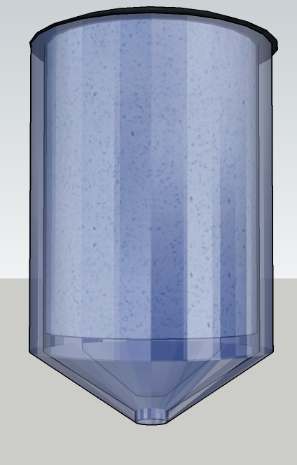
3D-Printed Show Model

3D-printed parts of the purification column.

We used a 3D-Printer to print the scaffold blocks and cut the front and back plate and the top and bottom hold bars by our self from acrylic glass. The glass slides were not biotinylated yet and the plates are not UV-permeable, so not usable, but the basis of further improvement and test of sealing and compatibility of the lab pumps. Besides the 3D-printed parts we cut and drilled the acrylic glass blocks and plates, the 3-mm threaded rods and the rubber mats at the home of a team member following our 3D-model.

Preparation of the non-3D-printed parts at the home of team member Markus.

We then assembled the parts and luckily everything matched as expected. The hand cut pattern of the rubber mat was still a bit uneven but should be still functional for some preliminary tests.

Inside and outside of the EluX prototype.

We were very happy that our first self-build model looks exactly like the 3D-modell and we were very excited to show it to some experts to gain some opinions and advices for the following design and construction of the application model.

Comparison of the build and presented show model and the 3D-Model.

We used this show model at our meetings with Prof. Dr. Dirk Lütkemeyer, General Manager of BIBITEC GmbH, and Dr. Benjamin Müller, CEO of Biofidus AG for Analytical Services. They advised us in building the shown models professionally to test and validate the system and also discussed the further development of the column and possible applications.

Elux: Theoretical basics

Affinity Purification columns

To purify specific target proteins out of the cell lysate, different approaches are adequate. One of the most common method (Mersha and England, 1997) is an affinity chromatography where the target protein is fused to a tag that binds specifically to a compound on the surface of the packed beads in the chromatographic column. In this case, different systems are in use, for example the highly specific and strong streptavidin-biotin-bond or the interaction between chitin-binding domains and chitin. When the cell lysate is loaded onto the column, the target protein will bind to the beads and all other proteins and cell fragments etc. will flow through the column. Afterwards, the target protein has to be eluted. For this, different methods can be used, for example by protease cleavage sides between the target protein and the tag or by loading a ligand onto the column which has a higher binding affinity than the tag itself. Also, harsh changes of the buffer condition like pH or salt concentration are used to elute proteins from affinity purification columns.

Workflow of the common procedure of an affinity purification process.

For purification overall it is desirable to have as few purification steps as possible because in every step a certain amount of the target protein gets lost, so that the yield of the purification system decreases dramatically (Mersha and England, 1997). Additionally, the tag has to be removed from the target, which might also need conditions harmful for the target or lead to a loss of the target.

Biotinylation of Silicon

The biotinylation of different surfaces is an important step in the production of materials useful for streptavidin-affinity-tags. One way is the biotinylation of proteins like BSA on their free amine-residues by covalent bond of the hydroxysuccinimide ester group of N-Hydroxysulfosuccinimide-Biotin. Alternately it is possible to biotinylate other surfaces like silicon oxide or glass with biotin if they contain free amine-residues on the surface. For this purpose, it is necessary to hydroxylate the surface for example with piranha acid (3:1 H2SO4:H2O2) and then treat the hydroxylated surface with APTES (3-aminopropyltriethoxysilane) (Acres et al., 2012).

Hydroxylation of a silicon surface with piranha acid and treatment with APTES do get free amine-residues on the surface, followed by biotinylation with NHS-biotin.

The APTES contains silicon oxide residues that can bind covalently to the silicon hydroxide. The APTES also contains the amine-residues on which the NHS-biotin can bind to biotinylate the glass surface that then can be used for streptavidin-affinity-tags (Lapin and Chabal, 2009). In our project, we used this workflow for biotinylation of BSA to induce the immobilization of a GFP-streptavidin fusion protein on a 96 well plate. Additionally, the biotinylation of glass slides can be used to produce more robust and reclaimable biotin surfaces for affinity and binding experiments.

References

Acres, R. G., Ellis, A. V., Alvino, J., Lenahan, C. E., Khodakov, D. A., Metha, G. F., & Andersson, G. G. (2012). Molecular structure of 3-aminopropyltriethoxysilane layers formed on silanol-terminated silicon surfaces. Journal of Physical Chemistry. 116(10): 6289–6297.

Lapin, N. A., & Chabal, Y. J. (2009). Infrared characterization of biotinylated silicon oxide surfaces, surface stability, and specific attachment of streptavidin. Journal of Physical Chemistry. 113(25): 8776–8783. Mersha, F. and England, N. (1997). Single-column purification of free recombinant proteins using a self-cleavable affinity tag derived from a protein. Gene. 192(2): 271–281.