Difference between revisions of "Team:Bielefeld-CeBiTec/Hardware"

Line 33: Line 33:
 
<h4> BSA-coated micro well plate  </h4>
 
<h4> BSA-coated micro well plate  </h4>
 
<article>
 
<article>
                     Before we had the idea of a <a href="https://2017.igem.org/Team:Bielefeld-CeBiTec/Project/toolbox/photolysis#LIE"> light-induced elution </a>, we wanted to prove and analyze the efficiency of the light induced backbone cleavage with a micro well plate coated with biotinylated BSA, because this is very common in lab everyday life. At this stage, we already had the idea to irradiate the plate with our <a href="#">LED-panel</a>  and so the panel was designed in the microwell format, such that other teams can use it for other microwell experiments.  
+
                     Before we had the idea of a <a href="https://2017.igem.org/Team:Bielefeld-CeBiTec/Project/toolbox/photolysis#LIE">light-induced elution</a>, we wanted to prove and analyze the efficiency of the light induced backbone cleavage with a micro well plate coated with biotinylated BSA, because this is very common in lab everyday life. At this stage, we already had the idea to irradiate the plate with our <a href="#">LED-panel</a>  and so the panel was designed in the microwell format, such that other teams can use it for other microwell experiments.  
 
                 </article>
 
                 </article>
 
                 <div class="figure small">
 
                 <div class="figure small">

Revision as of 12:37, 27 August 2017

Overview

Purification Column EluX

One of the non-canonical amino acids (ncAAs) we decided to integrate into our toolkit is 2-nitro-phenylalanine (2-NPA). This ncAA is very interesting to us, as it has the ability to induce a cleavage of the peptide backbone when radiated with light of ʎ = 365 nm wave length. This promises a wide field of possible applications. To demonstrate this astonishing feature, we use this ncAA tointroduce a protein purification system with light-induced elution as an alternative to protease cleavage sides. To put this idea in practice, we started the modelling of a purification column in SketchUp and constructed it with 3D-printed parts and acrylic glass. In this development process, we integrated many advices from professors and experts to render the model as efficiently as possible.
To verify the elution as easily as possible, we created a fusion protein containing GFP for a visible fluorescence signal and streptavidin to immobilize the protein in our column using biotin. The two protein parts are connected through a flexible glycine-glycine-serine-linker of eleven amino acids, in which the sixth amino acid is our 2-NPA. This ncAA will then induce the cleavage of our target protein (GFP) from the streptavidin compound in the purification process.

Development

Purification Column EluX

To demonstrate the usage of our non-canonical amino acids 2-nitrophenylalanine we aimed to construct a purification column that can induce the elution of the target protein by irradiation with light. In the development process, our column went through different design stages. Here we document the evolution of our column from the first idea, via different models we discussed and improved over the time, up to the final version we tested and presented to experts in order to get an idea of how our system could be used properly in the future.

Figure 1: The six steps in the development process of the purification column
A) BSA-coated micro well plate, B) Hollow cylindrical column, C) Biotinylated microscope slides, D) First flow model, E) second flow model, F) future concept of a microfluidic like column.

BSA-coated micro well plate

Before we had the idea of a light-induced elution
, we wanted to prove and analyze the efficiency of the light induced backbone cleavage with a micro well plate coated with biotinylated BSA, because this is very common in lab everyday life. At this stage, we already had the idea to irradiate the plate with our LED-panel and so the panel was designed in the microwell format, such that other teams can use it for other microwell experiments.

Figure 2: Concept of a microwell plate coated with biotinylated BSA.

Soon we realized how big the potential of this ncAA is, and what diverse uses are thinkable. We were inspired by a paper from Peters et al. [3] which described the cleavage of a short linear model peptide. We picked up this idea and thought about this model peptide as a protein linker to design a novel elution technique as an alternative to protease restriction sides. To realize this idea, we started in designing our own purification column.

Cylindrical column

Soon we realized how big the potential of this ncAA is, and what diverse uses are thinkable. We were inspired by a paper from Peters et al. [3] which described the cleavage of a short linear model peptide. We picked up this idea and thought about this model peptide as a protein linker to design a novel elution technique as an alternative to protease restriction sides. To realize this idea, we started in designing our own purification column.

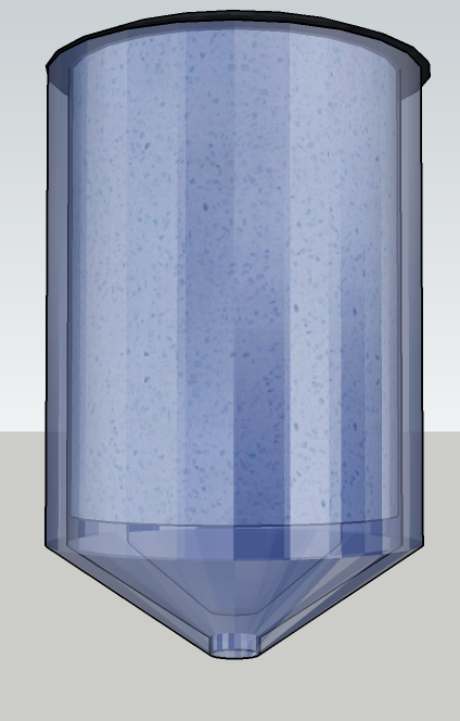
Figure 3: Concept of our cylindrical column
3D-Modell of a hollow column with an LED-rod in the middle and a carrier material coated with biotinylated BSA as first concept of a purification system using 2-NPA.

For an elution mechanism aiming on purification, it is also crucial to reach a high value of purity. We decided that it would be better to use a directly biotinylated glass plate instead of a BSA-coated carrier material, such that the BSA could be eluted in the purification process and would not be covalently bound to the surface.

Biotinylated glass slide

There is a way to directly biotinylate glass slides by hydroxylation and a treatment with APTES so that NHS-Biotin can bind covalently on the surface. We aimed at biotinylation of a whole glass slide in size of a microwell plate and irradiate it with UV-light through our LED-Panel also designed for a usage in microwell plates. Then we consider it would be better to treat a higher number of smaller glass slides and assemble them to a column.

Figure 4: Three microscope glass slides as basis for biotinylated surfaces for the purification column.

As we were sure that this would be a practical way to bind, irradiate, and elute our protein of interest, we thought about ways to design a purification column with many parallel glass slides instead of a hollow cylindrical one. This lead to a purification concept in which the surface of the column is crucial for the yield instead of the volume compared to conventional purification techniques.

First flow model

We designed our first flow model of the column by stacking eleven biotinylated microscope slides parallelly above each other separated by blocks of acrylic glass. Two big blocks on top and at the bottom of the column close the system. There are also holes to implement a pump system. To irradiate the slides properly, we used our self-designed microwell plate like LED-panel where a row of LEDs fits precisely between two slides for the front. On the front and back side of the column scaffold, we have adjusted two UV permeable acrylic glass slides to let the light through and seal the column. On the back side, there is an aluminum plate that will reflect the light and thus ensure an evenly irradiation. The individual parts of the column are sealed through rubber.

Figure 5: EluX prototype one.
First flow model of a purification column with parallel biotinylated glass slides inside and UV-permeable acrylic glass plates in front and back to enable the radiation with light of 365 nm wave length.

To improve our first model, we talked to some lecturers of protein purification and related fields in order to get some feedback and ideas of how we could increase the efficiency of our column. We were advised to round up the inner sides of the acrylic glass blocks to grant a more evenly flow-through between the glass slides. We got also the required information to choose a matching port that is connectable to the pumps that are used in our labs to make the column compatible to the inventory.

Second flow model

Implementing the feedback of the experts mentioned above, we designed our second column version, which we wanted to build and test in a protein purification experiment. The second model contains the rounded inner sides of the scaffold blocks, and holes for threaded rods to tighten and seal the column up.

Figure 6: EluX prototype two.
Second flow model of a purification column as basis for a workshop and a 3D-printed model to test, evaluate and improve the concept of light induced elution.

We were able to build this version of our purification column as a self-made 3D-printed model. We also invented the hard- and software of an LED-panel to irradiate the column properly and control the elution process. With this test column, we met up with two experts in protein purification and analytics and discussed the further optimization of our concept. This led to another version of the column we have not been able to construct yet. However, we instead created a 3D-model to show it.

Future microfluidic / flow-bundle model

Since the consulted experts advised us to increase the area to volume ratio for efficient target protein purification, we developed a microfluidic-like model (figure 7a). Prof. Dr. Lütkemeyer proposed a bundle-like construction as an alternative. He mentioned that we could also improve our actual model by coating the glass slides with a porous material, e.g. carboxymethyl dextran, before biotinylating to increase the area of the glass surface (figure 7b).

Figure 7: Future concept of EluX.
Concept of a microfluidic like (a) and a bundle (b) purification column designed with the support of Dr. Benjamin Müller and Prof. Dr. Dirk Lütkemeyer as future prediction of how the procedure of light induced elution could be used.

We realize the suggested versions of our purification column via 3D-models to evaluate them. Beside the advantage of these concepts to solve the area-to-ratio-problem, both have certain challenges too. The channels of the micro-fluidic like column could be clogged by the cell fragments contained in the loaded cell lysate. To address this issue the lysate could be filtrated. Unfortunately, this could lead to a loss of the target protein and thus decrease the yield. The major challenge concerning the flow-bundle-like column is the irradiation of all channels. We designed bundles of 37 small channels to arrange them like honeycombs with LED-units between the bundles. To still guarantee appropriate elution efficiency, the minimal amount of light and the minimal irradiation time should be tested. We would like to identify conditions which guarantee the channels in the center of the bundle to get enough UV-light to induce the protein back bone cleavage through the 2-NPA.

Construction

Purification column EluX

For the construction of our purification column, we aimed for two different approaches. The first one was to build the column on our own, using a 3D-Printer to get the basic parts of the column. This was important, as we wished to provide the construction files to the iGEM community and enable other teams to use and improve our work. The second approach was to construct this column in a more professional way, and so we asked the technical workshop of our university for assistance. They helped us by cutting the parts more precisely and so improve the applicability of the column. This lead us to two versions of the purification column, a 3D-printed show model and the application model.

3D-Printed show model

We used a 3D-Printer to print the scaffold blocks and cut the front and back plate and the top and bottom hold bars by our self from acrylic glass. The glass slides were not biotinylated yet and the plates are not UV-permeable, so not usable, but the basis of further improvement and test of sealing and compatibility of the lab pumps.

Figure 8: 3D-printed parts of the purification column.

Besides the 3D-printed parts we cut and drilled the acrylic glass blocks and plates, the 3-mm threaded rods and the rubber mats at the home of a team member following our 3D-model.

Figure 9: Preparation of the non-3D-printed parts at the home of Team member Markus.

We then assembled the parts and luckily everything matched as expected. The hand cut pattern of the rubber mat was still a bit uneven but should be still functional for some preliminary tests.

Figure 10: Inside and outside of the EluX prototype.

We were very happy that our first self-build model looks exactly like the 3D-modell and we were very excited to show it to some experts to gain some opinions and advices for the following design and construction of the application model.

Figure 11: Comparison of the build and presented show model and the 3D-Model.

We used this show model at our meetings with Prof. Dr. Dirk Lütkemeyer, General Manager of BIBITEC GmbH, and Dr. Benjamin Müller, CEO of Biofidus AG for Analytical Services. They advised us in building the shown models professionally to test and validate the system and also discussed the further development of the column and possible applications.