Difference between revisions of "Team:MSU-Michigan/Results"
Amburn Brian (Talk | contribs) |
Amburn Brian (Talk | contribs) |
||
| Line 26: | Line 26: | ||
<div class="w3-container w3-center"> | <div class="w3-container w3-center"> | ||
<img alt="File:Induction picture -1.png" src="/wiki/images/thumb/c/c7/Induction_picture_-1.png/800px-Induction_picture_-1.png" style="width:100%" srcset="/wiki/images/thumb/c/c7/Induction_picture_-1.png/1200px-Induction_picture_-1.png 1.5x, /wiki/images/c/c7/Induction_picture_-1.png 2x"> | <img alt="File:Induction picture -1.png" src="/wiki/images/thumb/c/c7/Induction_picture_-1.png/800px-Induction_picture_-1.png" style="width:100%" srcset="/wiki/images/thumb/c/c7/Induction_picture_-1.png/1200px-Induction_picture_-1.png 1.5x, /wiki/images/c/c7/Induction_picture_-1.png 2x"> | ||
| + | </div> | ||
</div> | </div> | ||
</div> | </div> | ||
</div> | </div> | ||
| + | |||
| + | <div class="w3-cell-row"> | ||
<div class="w3-container w3-cell"> | <div class="w3-container w3-cell"> | ||
<div class="w3-card-4 w3-pale-blue w3-padding-large"> | <div class="w3-card-4 w3-pale-blue w3-padding-large"> | ||
| Line 39: | Line 42: | ||
</div> | </div> | ||
| + | |||
| + | <div class="w3-cell-row"> | ||
<div class="w3-cell-row"> | <div class="w3-cell-row"> | ||
<div class="w3-container w3-cell"> | <div class="w3-container w3-cell"> | ||
| Line 44: | Line 49: | ||
<div class="w3-container w3-center"> | <div class="w3-container w3-center"> | ||
<img alt="File:Induction picture -3.png" src="/wiki/images/thumb/6/6a/Induction_picture_-3.png/800px-Induction_picture_-3.png" style="width:100%" srcset="/wiki/images/thumb/6/6a/Induction_picture_-3.png/1200px-Induction_picture_-3.png 1.5x, /wiki/images/6/6a/Induction_picture_-3.png 2x"> | <img alt="File:Induction picture -3.png" src="/wiki/images/thumb/6/6a/Induction_picture_-3.png/800px-Induction_picture_-3.png" style="width:100%" srcset="/wiki/images/thumb/6/6a/Induction_picture_-3.png/1200px-Induction_picture_-3.png 1.5x, /wiki/images/6/6a/Induction_picture_-3.png 2x"> | ||
| + | </div> | ||
</div> | </div> | ||
</div> | </div> | ||
</div> | </div> | ||
| + | <div class="w3-cell-row"> | ||
<div class="w3-container w3-cell"> | <div class="w3-container w3-cell"> | ||
<div class="w3-card-4 w3-pale-blue w3-padding-large"> | <div class="w3-card-4 w3-pale-blue w3-padding-large"> | ||
Revision as of 23:39, 31 October 2017
Results


Success!
Sequencing confirmed that the T7A1 promoter was removed and the other seven
promoters were inserted in its place thus creating seven new strains of S. oneidensis MR-1. The
original IPTG inducible strain was used in the engineering protocol to test current and GFP
induction. After initial troubleshooting in the bioelectrochemical system design that caused
inconsistent current production (Figure 8), current induction by IPTG showed promising results.
Inconsistent current developed from hydrogen gas build-up in the counter electrode leading to
an extra 18 gauge being added to the counter electrode housing. Similar results would be
obtained if KCl is not removed from the glass reference housing or if bubbles form by the
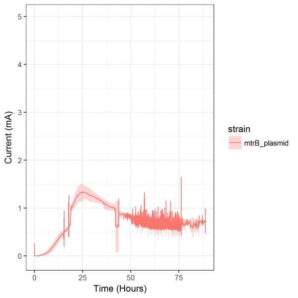
Magnesis stick inside the housing. ΔmtrB prL814-mtrB was induced with IPTG and showed
nearly two-fold increase in current while ΔmtrB prL814 and ΔmtrB produced only .03 mA of
current (Figure 1). The knockouts displaying lack of current production shows the importance of
the Mtr pathway and concurrently inducing transcription of mtrB on the plasmid that creates
current displays this as well. Background expression of mtrB due to the nature of the Lac
operon produced current up to .75 mA (Figure 1, 2, 3) before IPTG was added. Induction
comparison between when ΔmtrB prL814-mtrB is induced and when it is not induced showed
the difference between background expression and IPTG induction (Figure 2, 3). IPTG induction
earlier in experiment displays a more clear difference in current production between
background expression and induction. Viability of cells and pH impact could play a role in that
result but even late in the experiment IPTG induction still produces a current difference.
Fluorescence measurements showed repeatable IPTG induction of the GFP located on
prL814. M5 media provided background fluorescence measurements and displayed sterility of
the 96 well plate (Figure 4). ΔmtrB served as the negative control and showed the increase in
fluorescence due to growth in cells while showing no increase based on IPTG impact (Figure 5).
ΔmtrB prL814 and ΔmtrB prL814-mtrB both displayed increased GFP fluorescence with
increasing IPTG concentration (Figure 6, 7). ΔmtrB prL814 produced higher fluorescence than
ΔmtrB prL814-mtrB due to possible energy diversion towards producing MtrB. Both strains
showed the largest increase in fluorescence between 100 μM and 150 μM IPTG and saturation
starting at 250 μM (Figure 6, 7). Replicates between M5 media and the three strains show
consistency within the strains and sterility within the design of the 96 well plate and plate
reader set up.