Hardware
Create for wisdom of Life
1. Mircofluicdcs
Why we use microfluidics?
Traditionally, scientists often research the locomotion of Caenorhabditis elegans on the agar pad or the neurons of it after anesthesia. Via these methods, there is a clear imaging, but it is hard to detect a neuronal response and simultaneous behavior during movement. Thus, we came up with microfluidics to research worms. Microfluidics is a powerful technology that can integrate a number of functions in a plate of very tiny scale, which is best matched with the size of C. elegans. Scientists have successfully achieved high-through imaging and screening of worm populations with this technology [1]. Inspired by that, we designed two microfluidic chips to study the development of learning behaviors of C. elegans, aimed at not only a group of worms but also an individual one.
Despite the fact that worms are confined in chips, pushed by the fluid, the channels are specially designed to stimulate their normal movement. The material of the chips PDMS is transparent, and it has no influence on our discovery and measuring of light in optogenetics experiment. Gas molecules, diacetyl and 2-nonanone, can diffuse in PDMS so that the worms can sense the odor of such molecule. As a result, we can observe their preference on these odors.
The design of microfluidics
1.1 The Selective Chip
There are no more than one stages worms in one NGM plate. Thus, in order to obtain the best experimental results, we need to select appropriate stages of worms. And the best choice is worms in the L4 stage. But how to distinguish them in different stages? The simple method is to observe their size. Worms in L4 stage have medium size with a crescent-shaped uterus in their belly.
There are two plans of selecting worms. The first one is using microfluidics. And at the beginning of this chip, there are 12 holes and the worms of medium and small size can pass through them, remaining large sized worms at the right chambers. At the end of the chip, there are also 12 holes, but they are too narrow to pass through for the medium sized worms. Thus, the small sized worms can go out of the chip with the flow and the medium sized worms remain in the medium chamber. (Figure 1) We can get them by injecting the flow from the bottom entry to the top exist.
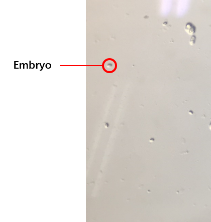
The second plan is to do the synchronization of worms, which is utilized to get a large number of worms at the same stage (链接到微流控protocol).We get the embryos (Figure 2) from the old worms so that they would grow up at the same stage because the time of these embryos’ hatches are at same. We try several protocols of the synchronization. And finally, we obtain the best protocol to select worms at the same stage. And our synchronous rate can reach to about 80%.
Compared with these two methods, we think the synchronization of worms is better. And you can get more detail results by click here. (https://2017.igem.org/Team:SUSTech_Shenzhen/Results)
1.2 The Gaussian Chip
In order to study locomotion of C. elegans populations, scientists have designed a pillar-filled area, where the pillars are designed such that they allow crawling-like behaviors even though worms are immersed in liquid environment[2].(Figure 3)
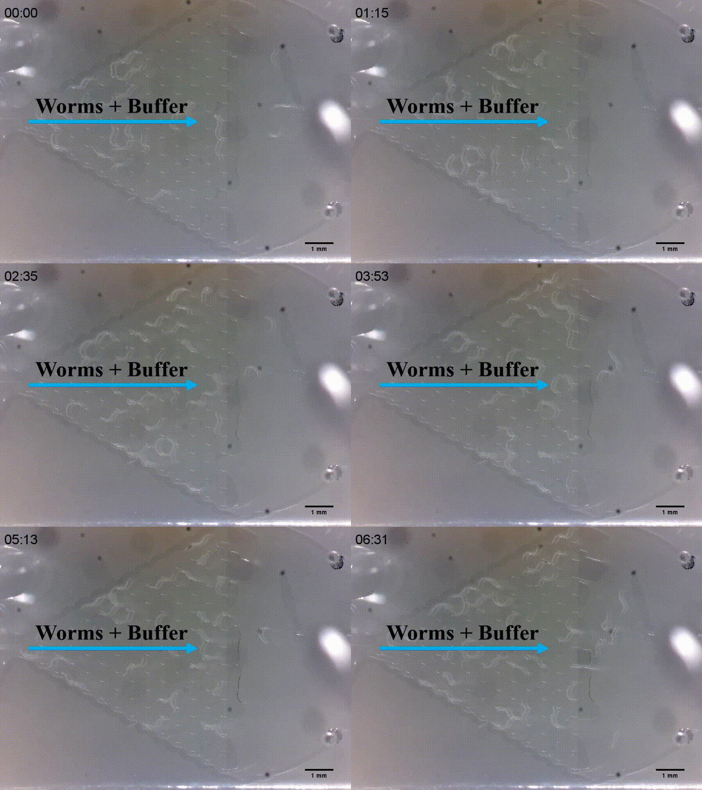
Moreover, the locomotion of C. elegans are like a waveform, so the width and angle between pillars are so optimal that worms can more efficiently move. After deciding to use this kind of microfluidics, we were inspired that it was like the Galton board[3]. (Video 1)
There is a hypothesis the possibility for C. elegans choosing the left or the right is equal when it passes through a crossroad. And then we could assume that C. elegans was similar to beans in the Galton board. If we push wthusorms by slow buffer current in a horizontal plane, it is like a gravity acted in beans. Both of their results may be the Gaussian distribution ideally. (Figure 4)
Given that we were not sure whether our insertions will influence the olfactory receptor neuron pair after C. elegans being injected our target gene, we needed to use Gaussian plate to prove their original preference for diacetyl and 2-nonanone. Thus, we injected a kind of chemical named diacetyl that C. elegans prefers into the right channel (or the left channel). Because of the diffusion, the right side is filled with these chemicals. Most of C. elegans would like to tend to that side, causing Gaussian distribution changed in variance and mean value. The ideal result is following figure. (Figure 5)
And for the diffusion, we also have two methods to make a concentration gradient in Gaussian plate. The first one is to add chemicals at the same plate in the right (or left) channels (Figure 6).
And the second one is to add chemicals above. That means we put a “cover” on the Gaussian plate (Figure 7).
And we can make the concentration gradient in this cover. Because of the diffusion, we can get the same concentration gradient on the Gaussian plate to observe changed distribution (Figure 8).

1.3 The Immobilization Chip
After studying worms’ behaviors of populations and proving their olfactory neurons are not being influenced, we could research their individual neuron and behavioral response. Typically, anesthetics or glues was utilized to immobilize worms. But it was damaged and tough to study its behavioral response. Thus, we designed two kinds of microfluidic chips to allow high-resolution microscopic imaging on chip without any damage for worms. (Figure 9)
The first one is used to research the imaging of neuronal response, called worm clamps or traps[4].In this case, a channel larger than the worm’s diameter is tapered to an opening of 30 um or less (for worms in the L4 stage). (Figure 10) Worms are trapped in the wedge-shaped channel. Trapped worms can then be released by reversing the flow. The traps allow worms’ movement in x-y plane but restrict it in z direction, and it is also utilized to study the contraction and elongation of their heads and research the neuronal activity by detecting calcium indicator GEM-GECO in imaging software.
The next channel is compressed and rectangular, called parallel channel. Immobilization by compression takes advantage of the flexibility of PDMS, which can be compress by the pressure of water or air. Based on this principle, we design two gas valves to block the exit and entry for worms in chips. When worms go into the parallel channel, we turn off the gas valves immediately by increasing the pressure in control layer. The width between control layer and flow layer is so narrow that it is easy to make flow layer bend and block the exit and entry. (Figure 11) [5]
In this kind of channel, worms can also be restricted in z direction and just move forwards or backwards. We activate worms by using red light and blue light. And in our design, if we use blue light, worms will attempt to approach the light. If we use red light, they will go away from the light.
The contents above are our all hardware parts in microfluidics. If you are interested in our results, please click here. (放result的链接!)
2. Play with light in spatio-temporal
Multiple devices of optics are designed and created for the various requirement of experiments. All devices are attempt to modulate the spatio-temporal pattern elegantly and effectively. Just let us start to play with light.
2.1 Device One: Arduino modulate Mercury lamp
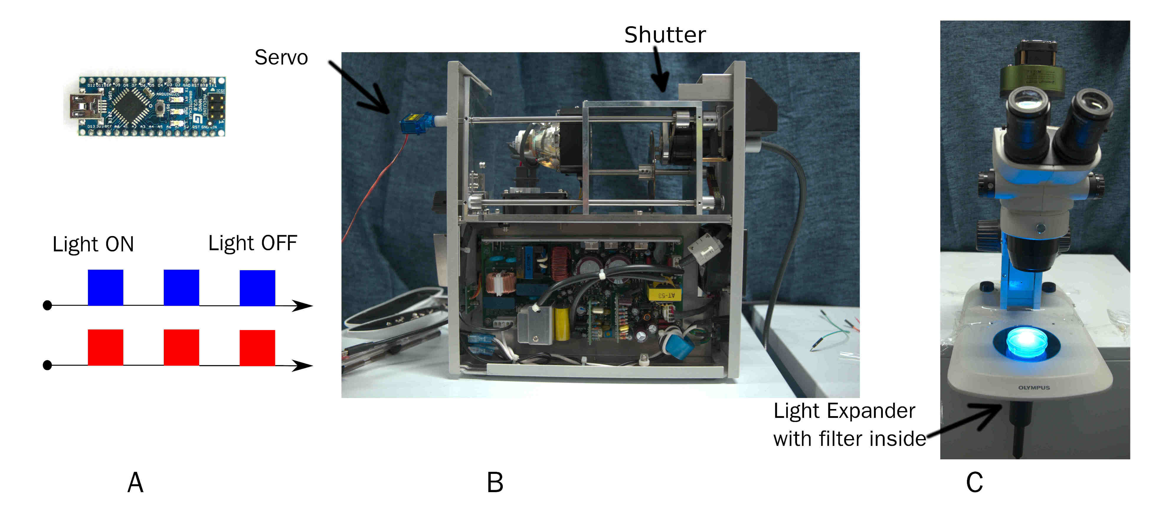
A simple and effective device to output pulse of certain wavelength of light. On time and off time of pulse is custom by Arduino. Wavelength of light is changed by replacing filter before beam expander.
2.2 Device Two: Projector Tracker
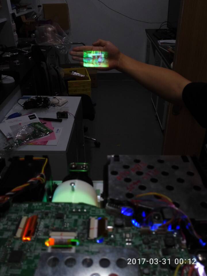
Here is a more fantastic and powerful tool with a LCD Projector we design.
2.2.1 Basic mechanical and optics
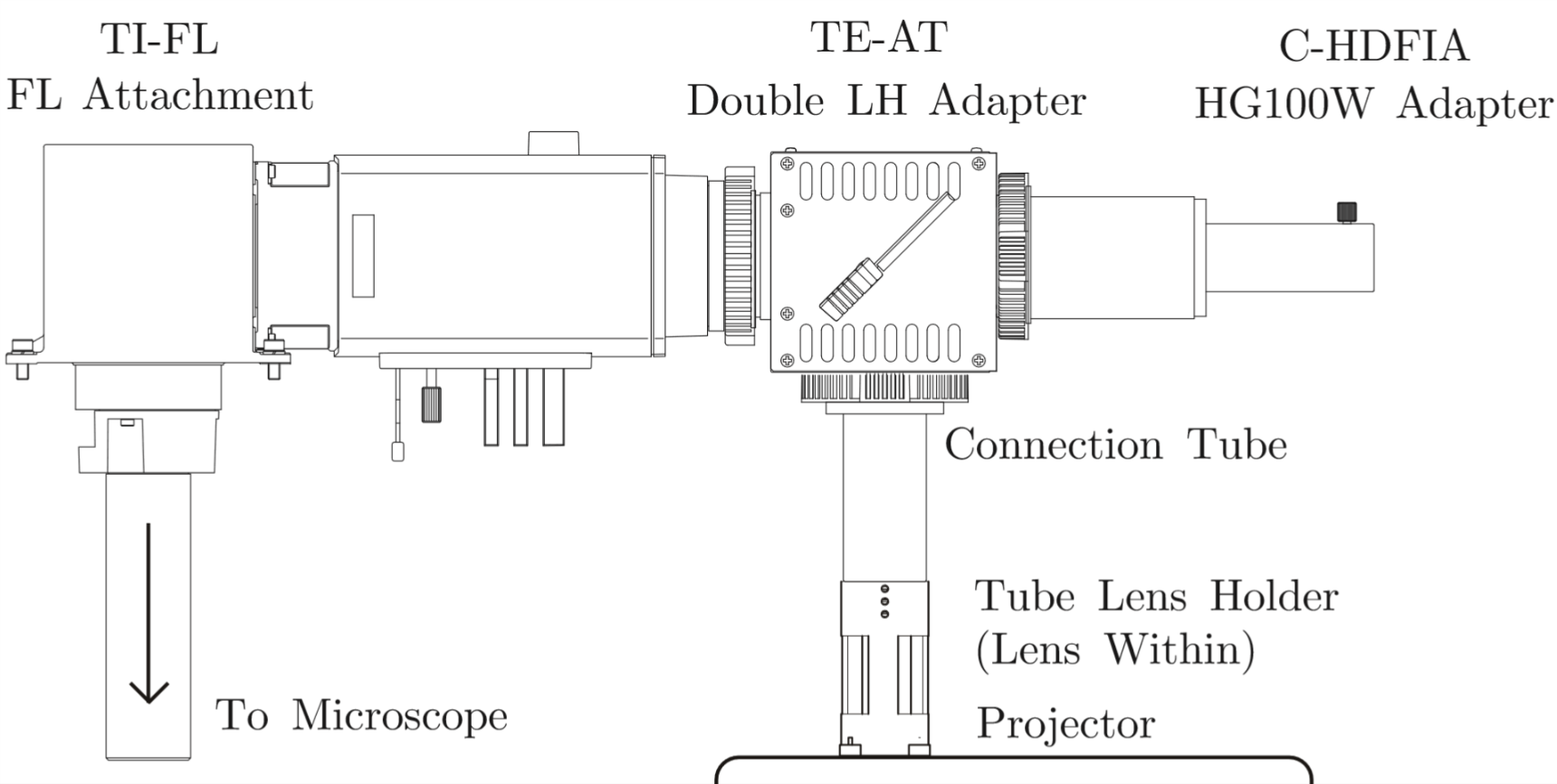
We need 395nm light to activate Calcium indicator protein GEM-GECO by Lumencor LED Illuminator. Then CoChR and Chrimson are activated by blue light and red light from LCD projector. LCD projector and LED Illuminator are merged by a double LH Adapter contained a semi-transparent mirror. Double LH Adapter connect to entrance of light in microscope. So we can use these two light source in the same time.
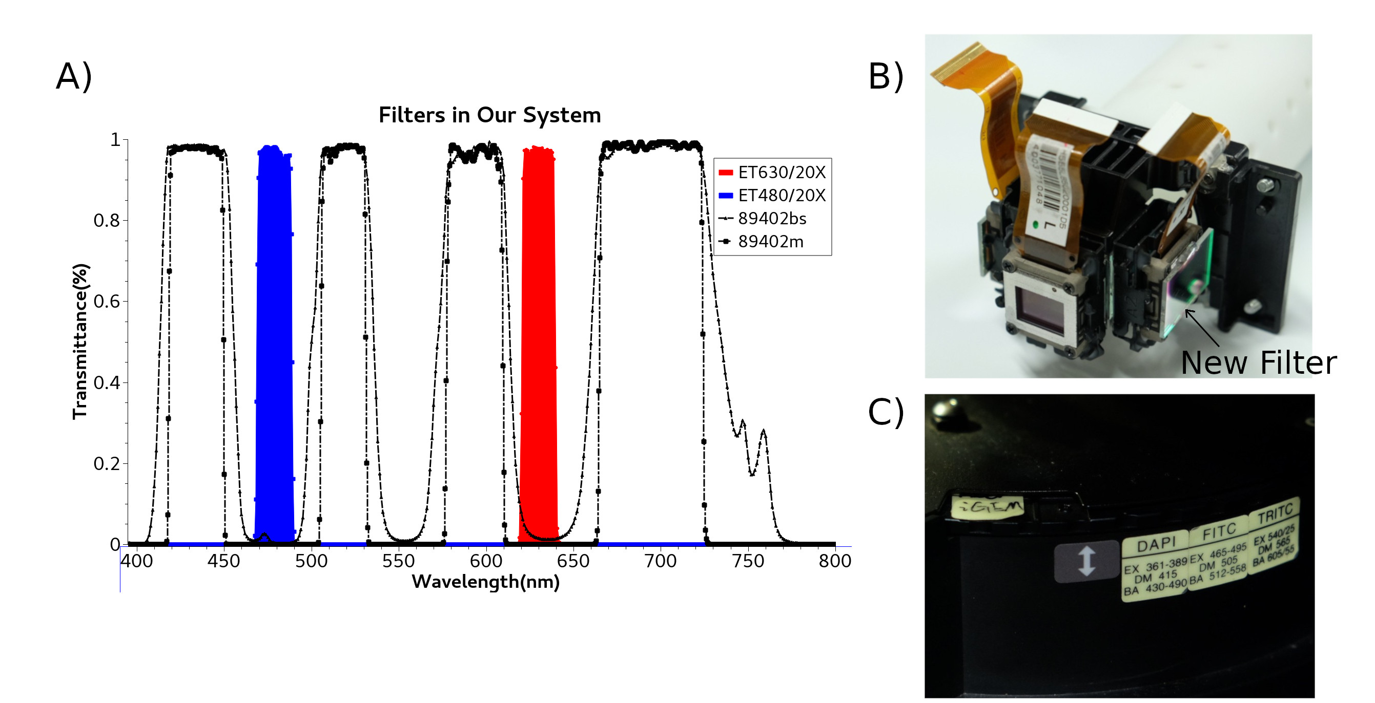
Protein are sensitive to the wavelength of light, it necessary to purify light of the projector. We buy and replace with new filter Chroma ET480/20X and Chroma ET630/20X, both are fixed inside projector. Di-mirror 89402bs and emission filter 89402m are been installed in Microscope filter wheel.
2.2.2 Control Software
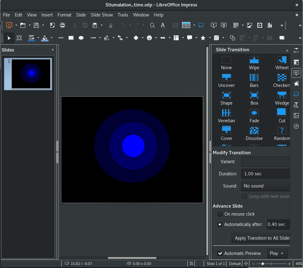
Software is most flexible part. A very easy knack is to use slide(Demo slide[1]), such as LibreOffice[2](Test on 5.4.2.2.0+ in Arch Linux) or Microsoft Office. The image and time pattern is stetted in slide, including color, intensity, pulse time etc.
We try develop a more challenged and hackable open source software suit called ColorMapping to track and activate multi C. eleganss or cell independently in one eye-filed. User can modify multi color, intensity, time, locations of light alternately in GUI. ColorMapping can be found in GitHub[3], which still is developing. ColorMapping contains camera part, projector part, user&calculation part. More detain can be found in GitHub Document and PDF[].
References
- ↑ Chung, K., et al. (2008). “Autom ated on-chip rapid microscopy, phenotyping and sorting of C. elegans.” Nature Methods 5(7): 637-643.
- ↑ Albrecht, D.R., and Bargmann, C.I. (2011). High-content behavioral analysis of Caenorhabditis elegans in precise spatiotemporal chemical environments. Nat. Methods 8, 599-605.
- ↑ Bean machine. (2017, October 5). In Wikipedia, The Free Encyclopedia. Retrieved 12:46, October 22, 2017, from https://en.wikipedia.org/w/index.php?title=Bean_machine&oldid=803992086
- ↑ Hulme, S. E., Shevkoplyas, S. S., Apfeld, J., Fontana, W., & Whitesides, G. M. (2007). A microfabricated array of clamps for immobilizing and imaging C. elegans. Lab on A Chip, 7(11), 1515.
- ↑ Unger, M.A., Chou, H.P., Thorsen, T., Scherer, A., and Quake, S.R. (2000). Monolithic microfabricated valves and pumps by multilayer soft lithography. Science 288, 113-116.


