Playing with Light in Space & Time
Let there be light!
Contents
Multiple optic devices are designed for the various experimental requirements, such as stimulating neuron of Caenorhabditis elegans, training C. elegans and inducing C. elegans to move in a certain direction. They can regulate output temporally and spatially in an elegant and efficient way.
Forming Pattern with Light
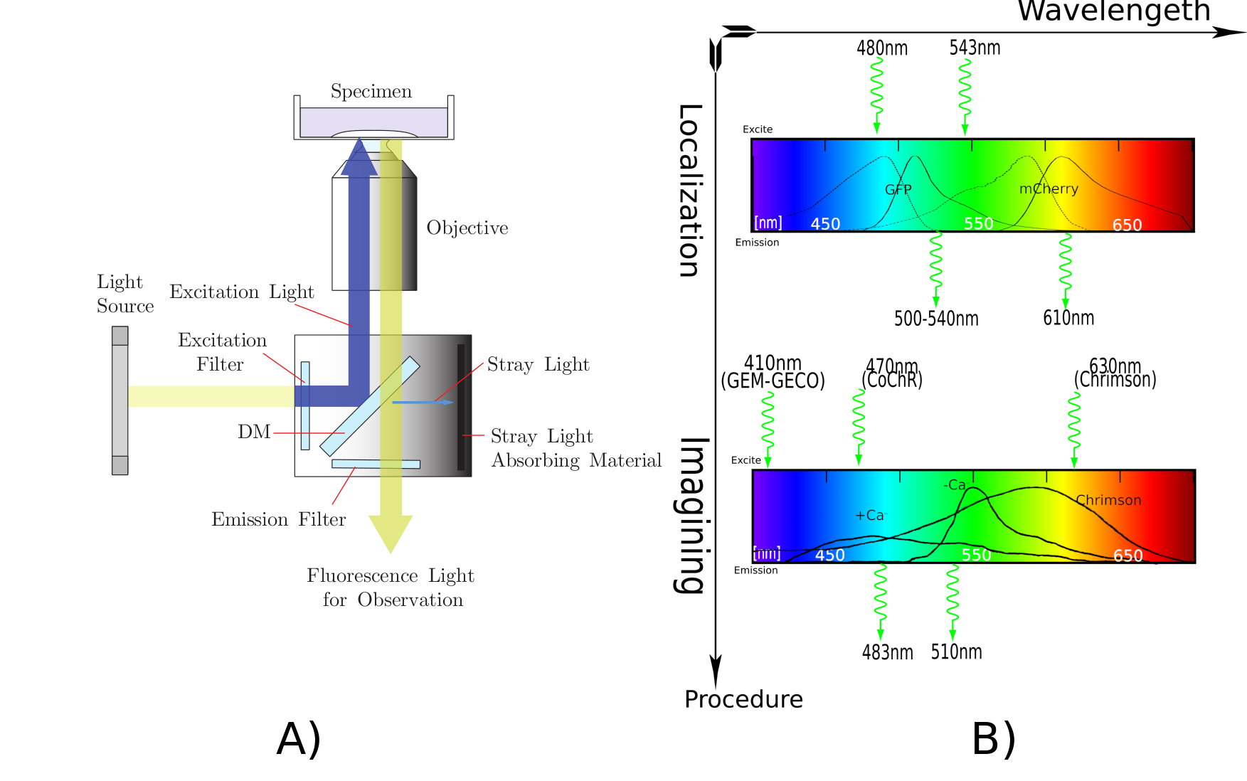
Biology background in our project: We need to use 395nm light to activate Calcium indicator GEM-GECO for neural activity imaging. For the independent excitation of neurons (AWA and AWB) in C. elegans, channelrhodopsins CoChR and Chrimson are activated by blue light and red light respectively [1]. Due to these proteins' selectivity to the wavelength of stimulating light, we need to "purify" the light from the projector.
Optical System
GEM-GECO is activated by 395nm light from LumencorSpectra LED Illuminator.
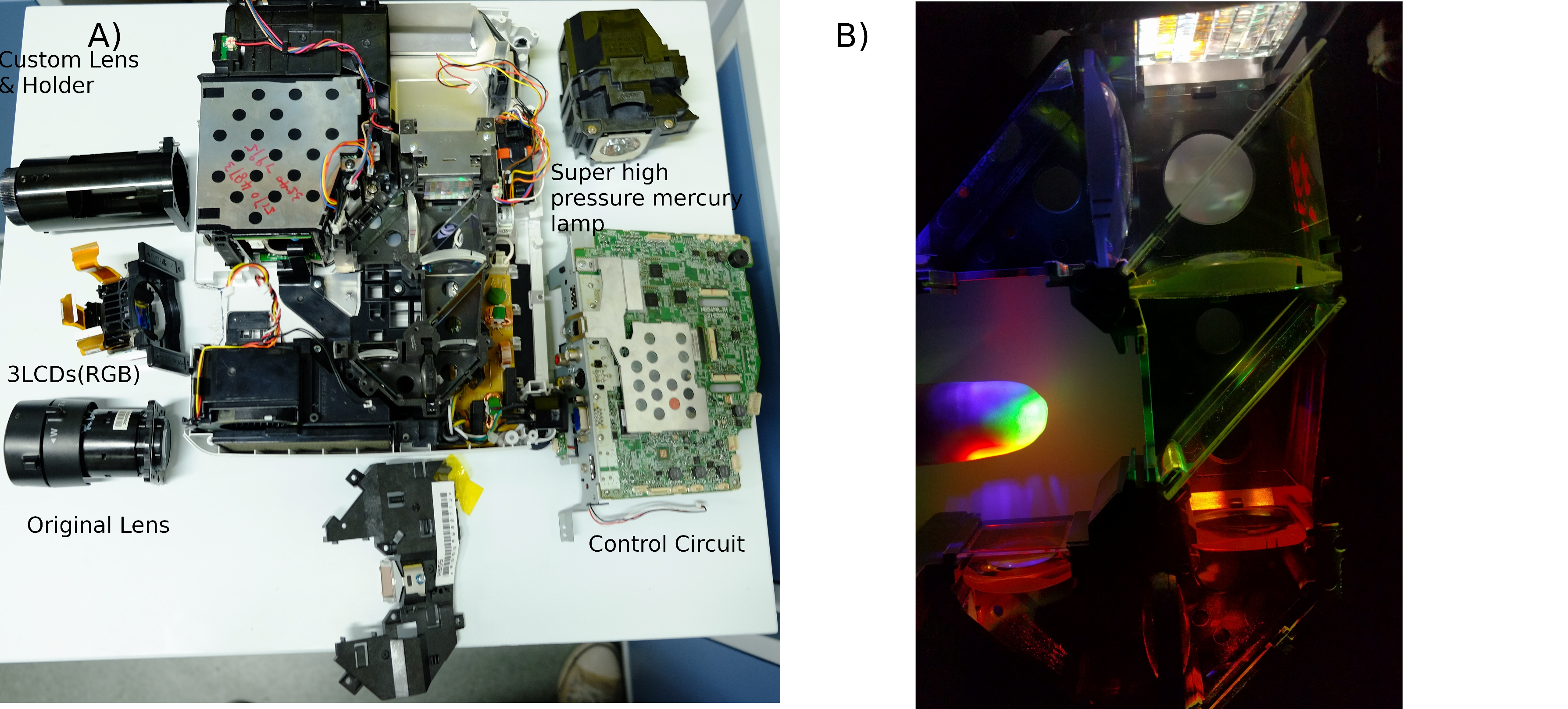
We use a [http://www.epson.com.cn/products/projectors/239/CB-X03/ EPSON CB-X03] LCD projector as the red & blue light sources for CoChR & Chrimson. The projector's 3 LCDs(red, green and blue channel) functions as 1024*768 electronic shutters in each channel. Projector's super high pressure mercury lamp functions as a high-intensity light source[Fig. 2].
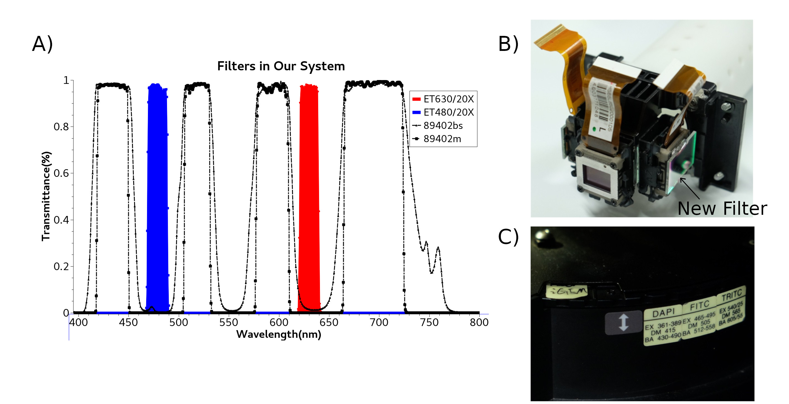
Firstly, we need to "purify" the light wavelengths of projector. Although the original filter can separate white light into red light and blue light, the bandwidth of red light or blue light is not narrow as what our optical sensory proteins(CoChR & Chrimson) require . We install additional red filter Chroma ET630/20X and blue filter Chroma ET480/20X outside 3LCDs. (Fig. 3B)
According to the principle of fluorescence microscope, corresponding Di-Mirror 89402bs and emission filter 89402m are installed inside the microscope filter wheel(Fig. 3C). You can see all filters we use in our project (Fig. 3).
System Integration
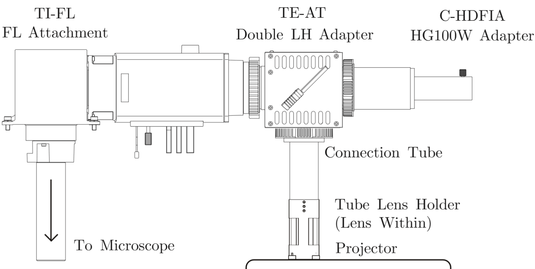
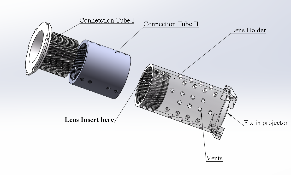
We need to install a new lens on projector with adjustable component, and fix all device with microscope stably.
Lens Holder and Connection Tube are design(Solidworks Documents) by CNC and 3D-Print(Fig. 6).
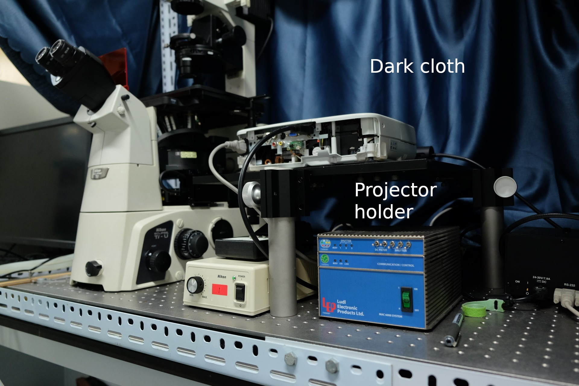
To build dark environment, we also build a dark room with cloth(Fig. 7).
Software Tool
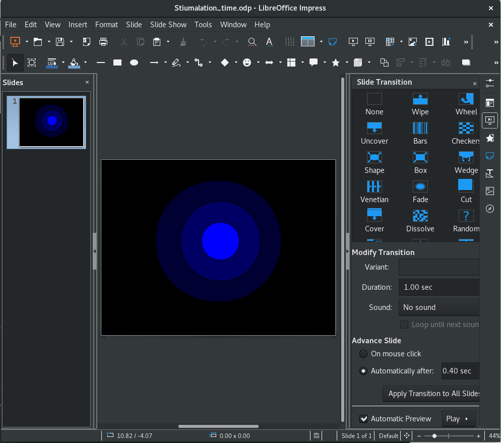
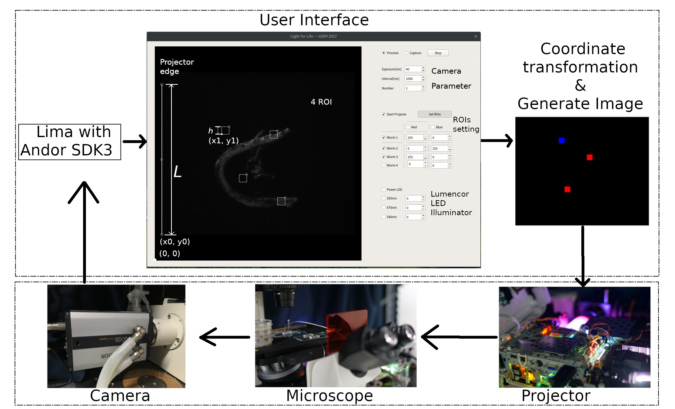
To control the ouput of light source, a software is required. However, a very easy method is using a slide(Demo Slide), such as LibreOffice(Test on 5.4.2.2.0+ in Arch Linux) or Microsoft Office. The image and time pattern is configured in slide, including color, intensity and pulse time etc.We also develop a more powerful and hackable open source software suite called ColorMapping to track and activate multiple C. elegans or cell independently in one view. User can modify multi color, intensity, time and locations of light alternately in GUI. Everyone is welcome to join us to develop ColorMapping in GitHub, which still is developing. ColorMapping, contains camera part, projector part, user&calculation part. It is coded by Python 2 Language, and third-party packages, PyGraph, PyQt5 and [http://lima.blissgarden.org/camera/andor3/doc/index.html?highlight=andor3 Lima(Library for Image Acquisition)]. ColorMapping tests on Arch Linux.
To drive Andor Zyla (5.2), we apply Andor SDK3 from Andor Company firstly. All data are matrix during data transfer and calculation. Camera image lives in user interface. In camera part, exposure time and other parameters can be adjusted.
An important algorithm is how to project a special area in special color. The key is coordinate system transformation between camera view(2560*2160) and projector(1024*768). To simplify the question, only the left projector edge and 4 ROIs(region of interesting) are drew. Every point(X_{projector}, y_projector) in the image will be generated from following formula(Fig. 10).
\left[\begin{matrix}x_{projector}\\y_{projector}\end{matrix}\right]= {\frac{1024}{L}}(\left[\begin{matrix}x_1\\y_1\end{matrix}\right]-\left[\begin{matrix}x_0\\y_0\end{matrix}\right])
In ROIs Setting, every ROI can define the color(Blue or Red) and intensity(0~255). 4 ROIs can move by mouse in real time, so the projector can response immediately. Generated image is showed a full-screen window in another extended desktop. Projector just show on extended desktop.
Generating Rhythm with Light
Biology background: To reduce the phototoxicity during train C. elegans, pulse of light is required rather than constant light[2].
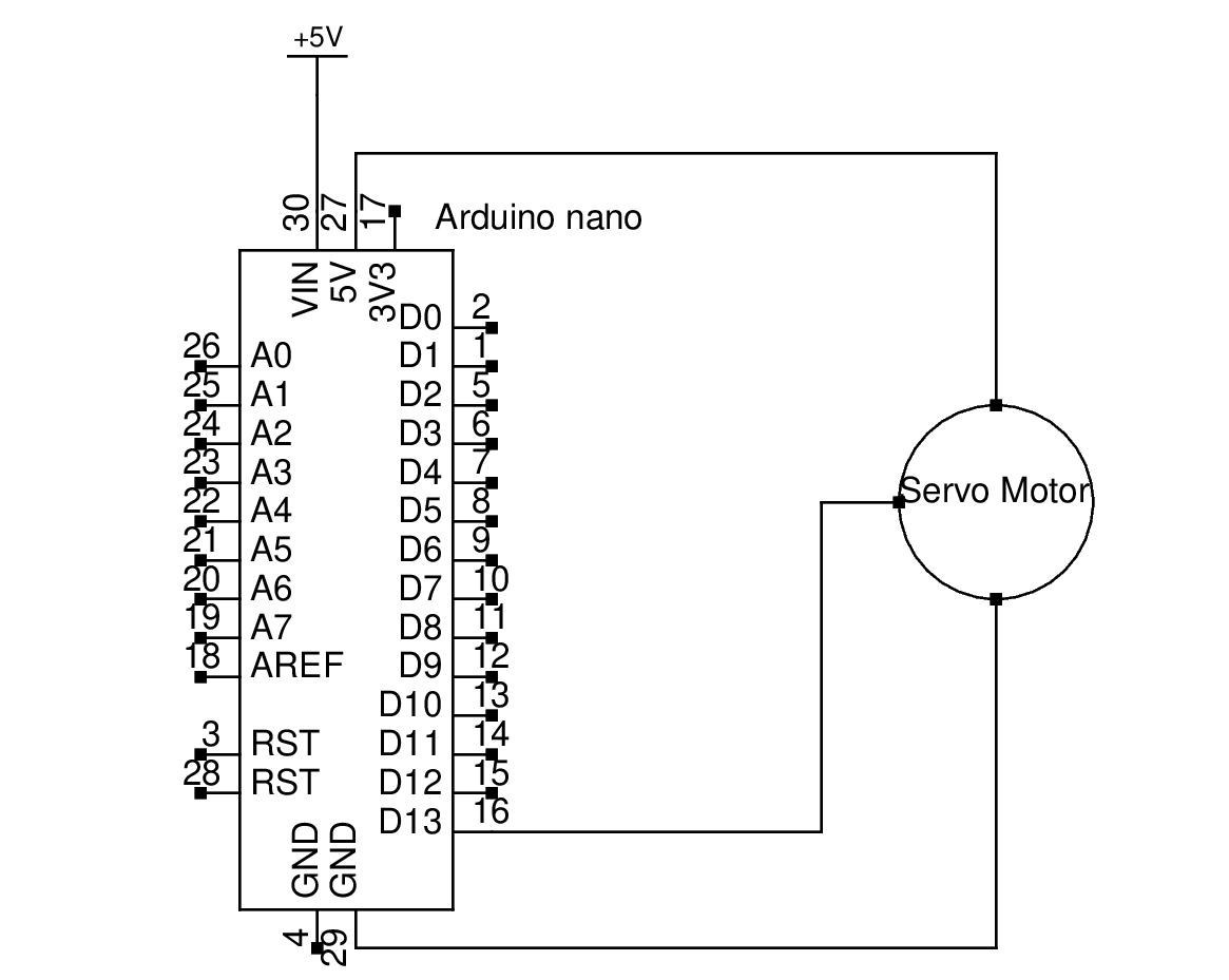
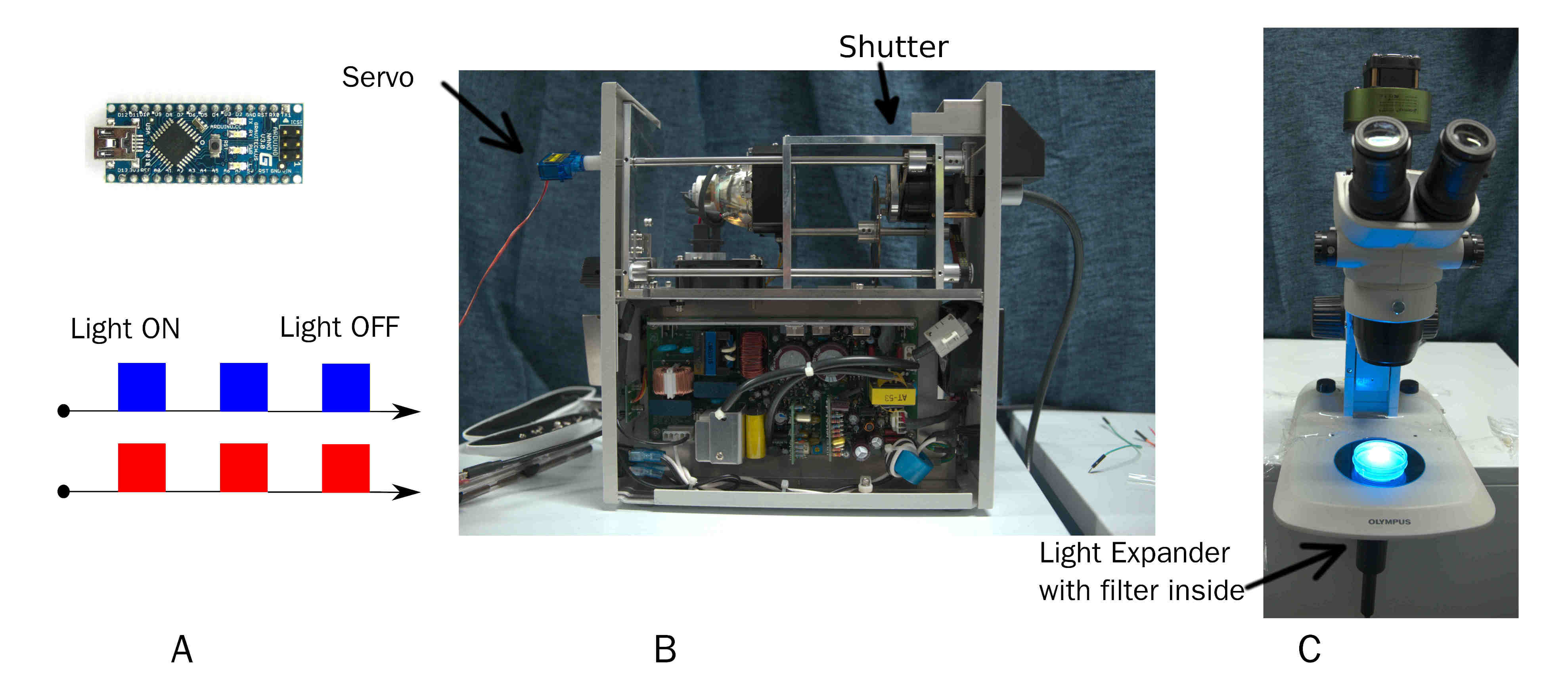
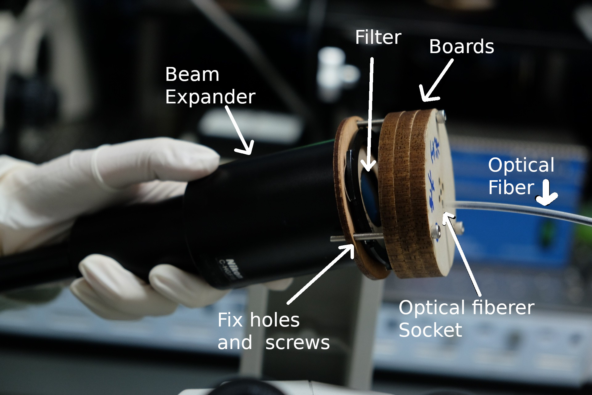
A simple and effective device output pulse of a certain wavelength of light. Arduino (A popular single-board microcontrollers) connect a servo, which is fixed in the shutter on mercury lamp by a 3D-print connector. When the servo motor rotates the shutter, on time and off time of the pulse is custom by Arduino . Wavelength of light is changed by replacing filter before beam expander(Fig. 12).
The 3D-print connector and Arduino code can download here. The result can be found in behavior result part.
Playing worm with Light
Because C. elegans expresses channelrhodopsins CoChR, C. elegans can move following the red light point in plate. We use optical fiber, boards and mercury lamp to build it.
. You can found the result in behavioral experiments partBill
Here are detail bill.
| Parts | Unit | COST/unit (CNY) | COST (CNY) |
|---|---|---|---|
| EPSON | 1 | 3960 | 3960 |
| CNC Components | 1 | 600 | 600 |
| Precise 3D-print Component | 1 | 213.22 | 213.22 |
| Optical plate | 1 | 230 | 230 |
| Lifting columns(GCM-2211) | 3 | 210 | 630 |
| Arduino nano v3.0 | 1 | 13.50 | 13.50 |
| Tower-Pro Servo | 1 | 8 | 8 |
| Filter 89402bs | 1 | 3159.45 | 3159.45 |
| Filter ET480/20X | 1 | 2161.73 | 2161.73 |
| Filter ET630/20X | 1 | 2161.73 | 2161.73 |
| Emission Filter 89402 | 1 | 2161.73 | 2161.73 |
| TOTAL (CNY) | 15299.36 | ||
| TOTAL (USD) | 2312.62 |
References
- ↑ Lisa C. Schild and Dominique A. Glauser , Dual Color Neural Activation and Behavior Control with Chrimson and CoChR in Caenorhabditis elegans, 2015, GENETICS.
- ↑ Venkatachalam, V., & Cohen, A. E. (2014). Imaging GFP-Based Reporters in Neurons with Multiwavelength Optogenetic Control. Biophysical Journal, 107(7), 1554–1563. http://doi.org/10.1016/j.bpj.2014.08.020


