Microfluidics
Create for wisdom of Life
Contents
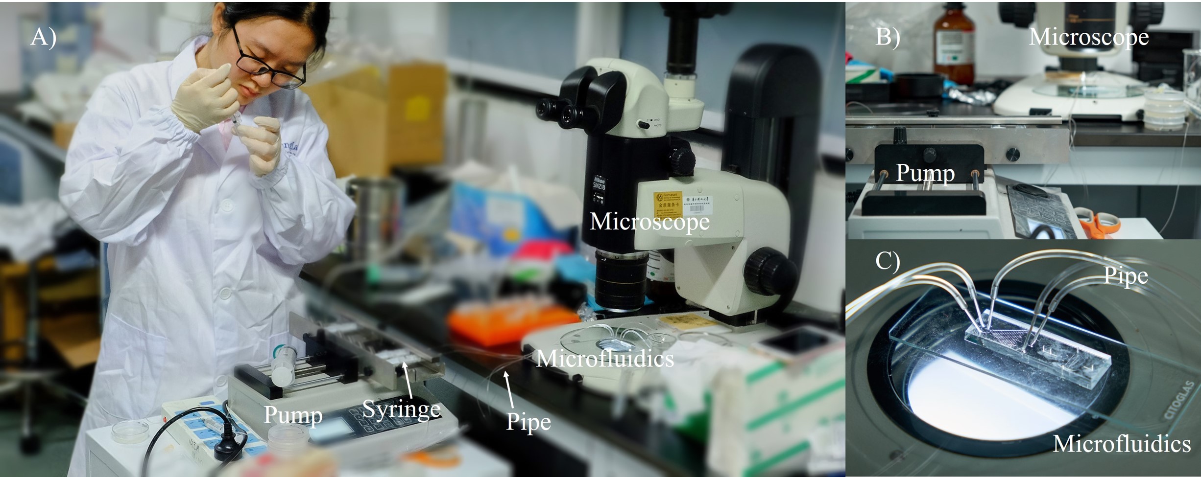
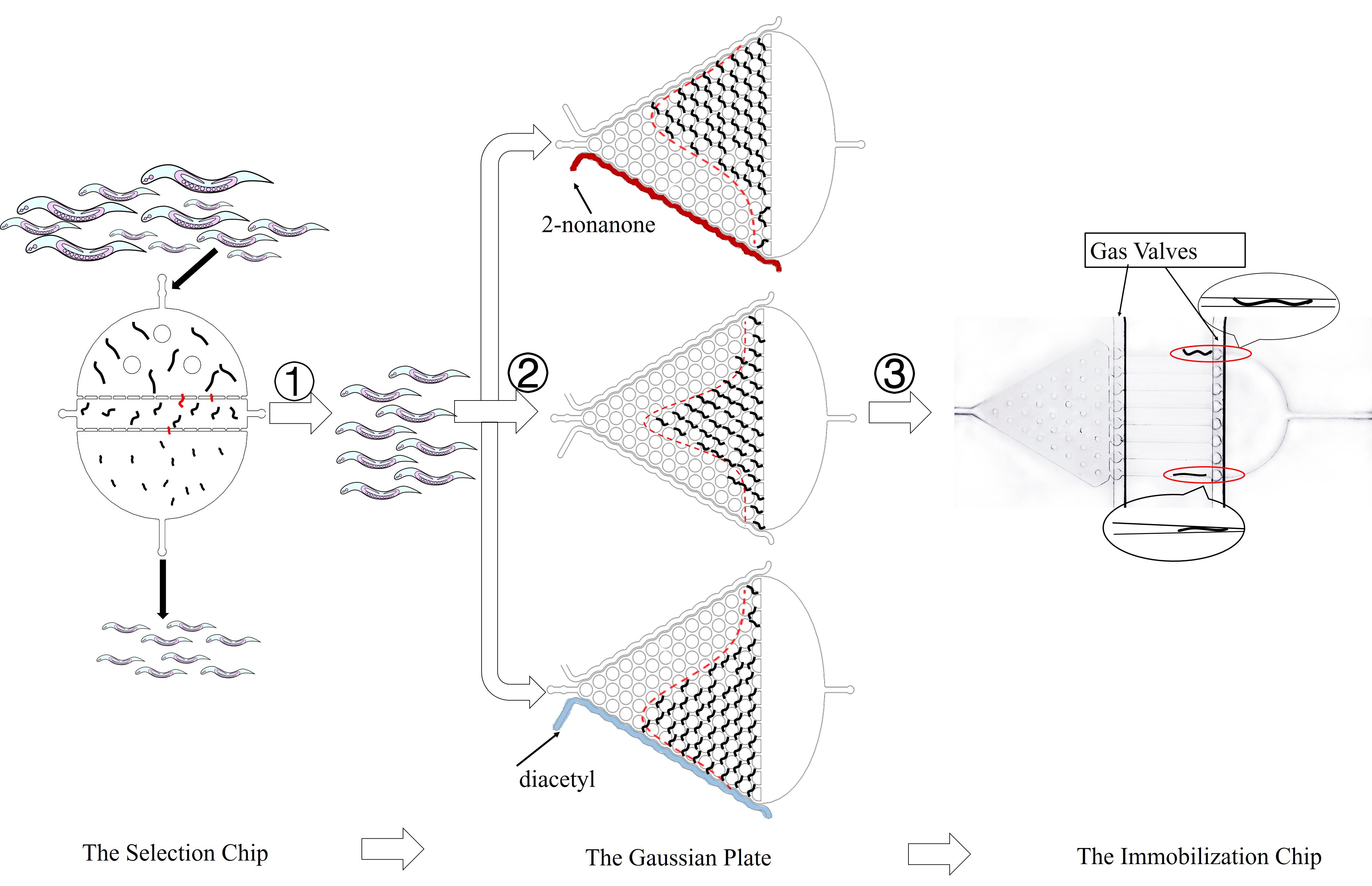
Currently microfluidics is actively used for both routine testing and academic researches. It consists of systems that work with small volumes of fluids in the nanoliter/microliter scale, through channels ranging from tens to hundreds of micrometers in diameter. Using this system, we can study the collective behavior of Caenorhabditis elegans groups as well as live neuron activities accurately. (Fig. 1)
In order to observe whether there are any changes in worms’ behavior after incorporating exogenous genes, we need to design a microfluidic system with high throughput and guarantee the worms are in natural conditions. Thus, we design the Gaussian Plate to monitor the changes.
In addition, we want to test live worms’ neuron activities in this system. Therefore, we choose to implement a “semifixed” scheme, and design the Immobilization Chip to meet this goal. Exogenous genes can express well in worms at L4 stage. Thus, we need synchronous worms at L4 stage to get accurate experimental results, and we design the Selection Chip to screen worms. (Fig. 2)
Microfluidics Design
1 The Selection Chip
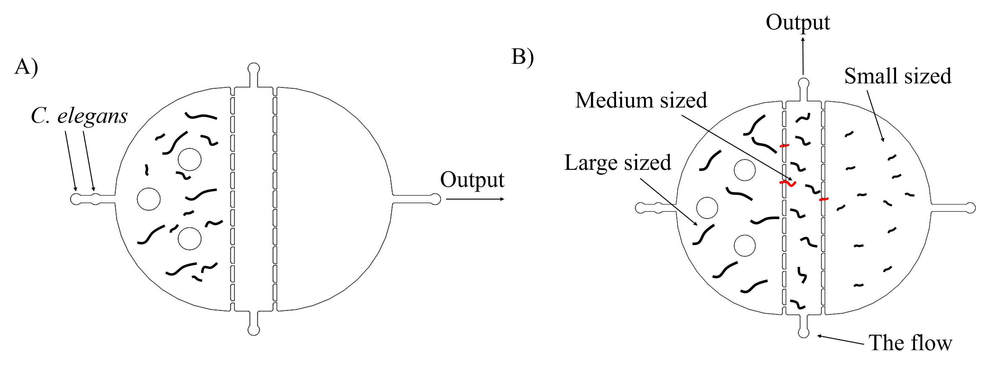
Previous reports show that exogenous genes will express well in worms at the L4 stage. Thus, we need to select worms at L4 stage to get the more suitable experimental group. The simple method is to distinguish them by sizes, because worms at L4 stage have medium sizes. Thus, we design two plans to screen worms.
The first one is to use microfluidics. With the flow filled with worms going through this chip, only the medium sized worms can remain in the medium chamber, and we could collect them by injecting the flow from the bottom and gather them in the top. (Fig. 3)
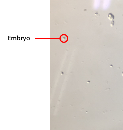
The second plan is to ensure the growth of worms synchronously, which is utilized to get a large number of worms at the same stage. Detailed Protocol We collect embryos (Fig. 4) by bleaching adults, and culture embryos to get a large number of worms at the same stage after three days. Our synchronous rate is calculated as the formula below.
\frac{N_1*100\%}{N_2}
N1 equals the number of worms at L4
N2 equals the number of all worms.
The successful synchronization rate can reach to about 80%.
Compared with those two methods in experiment, we find that we can get almost 50 out of 100 worms (One adult has no less than 3 embryos) in three days by the synchronization method, while we can just get 20 out of 100 worms in one day by microfluidics method. Given that we need a large number of worms to do the following experiment, we think the synchronization method is better. Detaied Results.
2 The Gaussian Plate
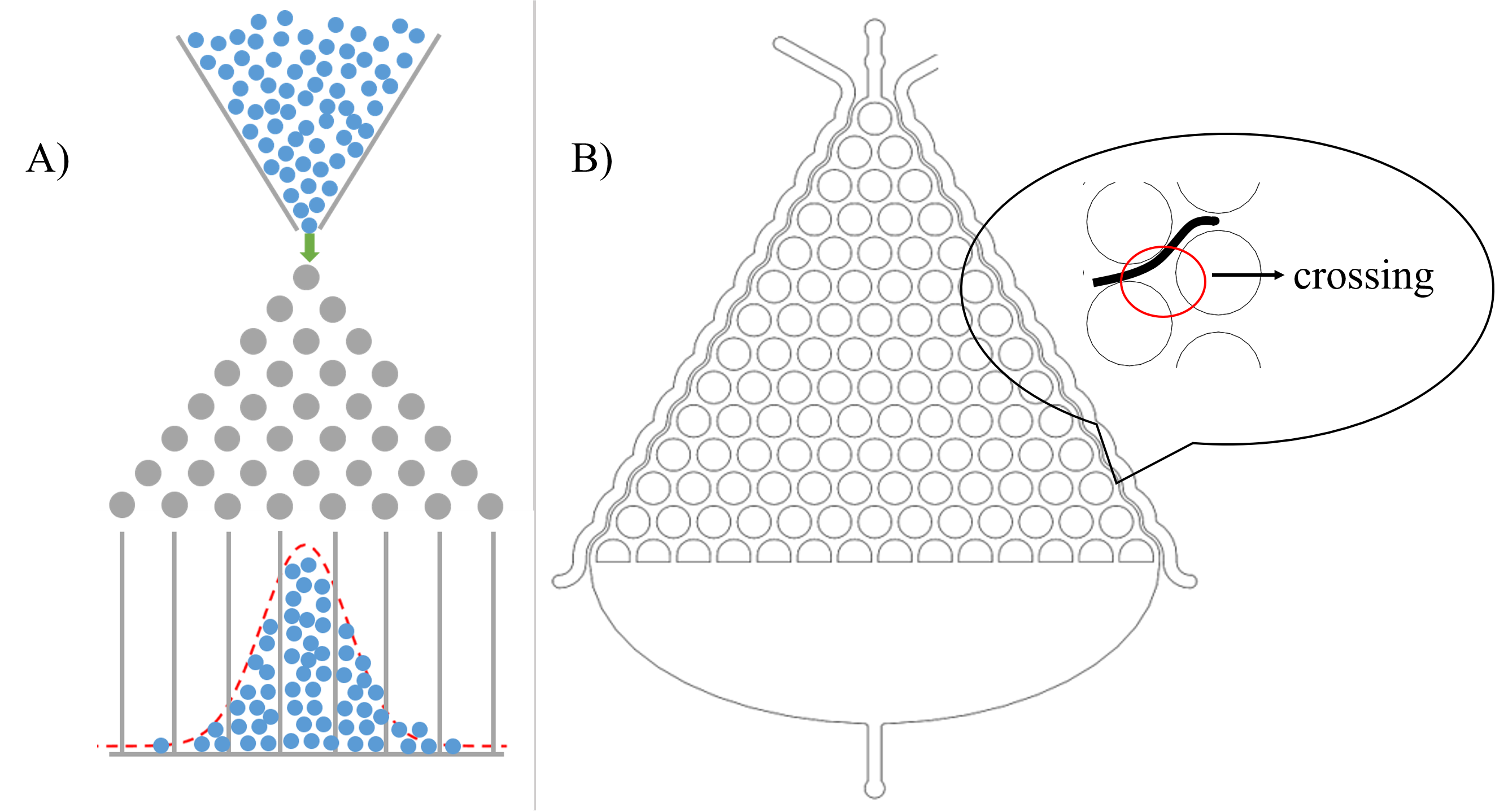
In order to study locomotive behavior of C. elegans populations, we design the Gaussian Plate, a pillar-filled area, where the pillars are designed such that they allow crawling-like behaviors even though worms are immersed in a liquid environment. (Fig. 5)[1]
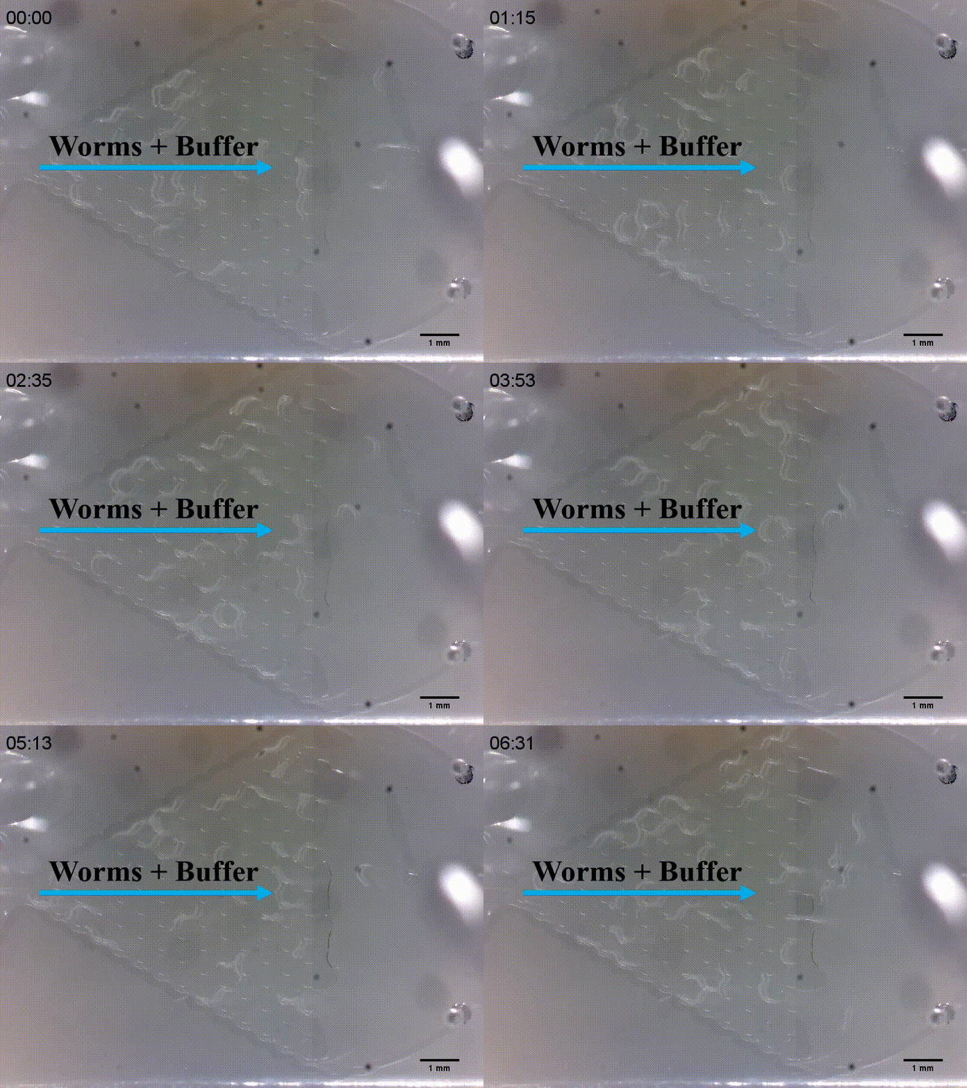
After deciding to use this microfluidics to study the locomotive behavior changes, we are noticed that the shape of microfluidics is similar to the Galton board.[2]. (Fig. 6(A)) Therefore, we assume that C. elegans is just like balls in the Galton board. The force of slow buffer flow acting on worms is the same as the gravity acting on balls. Moreover, the probability for C. elegans chooses to go left or right is equal when it passes a crossing. (Fig. 6(B))
Both distribution in the Galton board and the Gaussian Plate are Gaussian distribution. Based on these, we can monitor changes in worms’ distribution. We injected diacetyl (2-nonanone) that C. elegans prefers (repulse) into the right (left) channel to make a concentration gradient of the Gaussian Plate. Because of the gradient, worms tend to move to the side filled with diacetyl (or go away the side filled with 2-nonanone), causing Gaussian distribution changed. If changes happen, we can make sure that inserted target genes in C. elegans will not affect it olfactory receptor neuron pairs. (Fig. 7)
In order to make a concentration gradient, we come up with two methods to get it. (Fig. 8)
In order to simulate the process of diffusion, we make a diffusion model to guide us. More details. Detailed Model.
Both of those methods could be carried out theoretically. But in the process of experiment, we find the method 2 (Inject chemicals into layer 2) cannot make a stable concentration gradient. Thus, we use method 1 (Inject chemicals into the side of layer1).
3 The Immobilization Chip
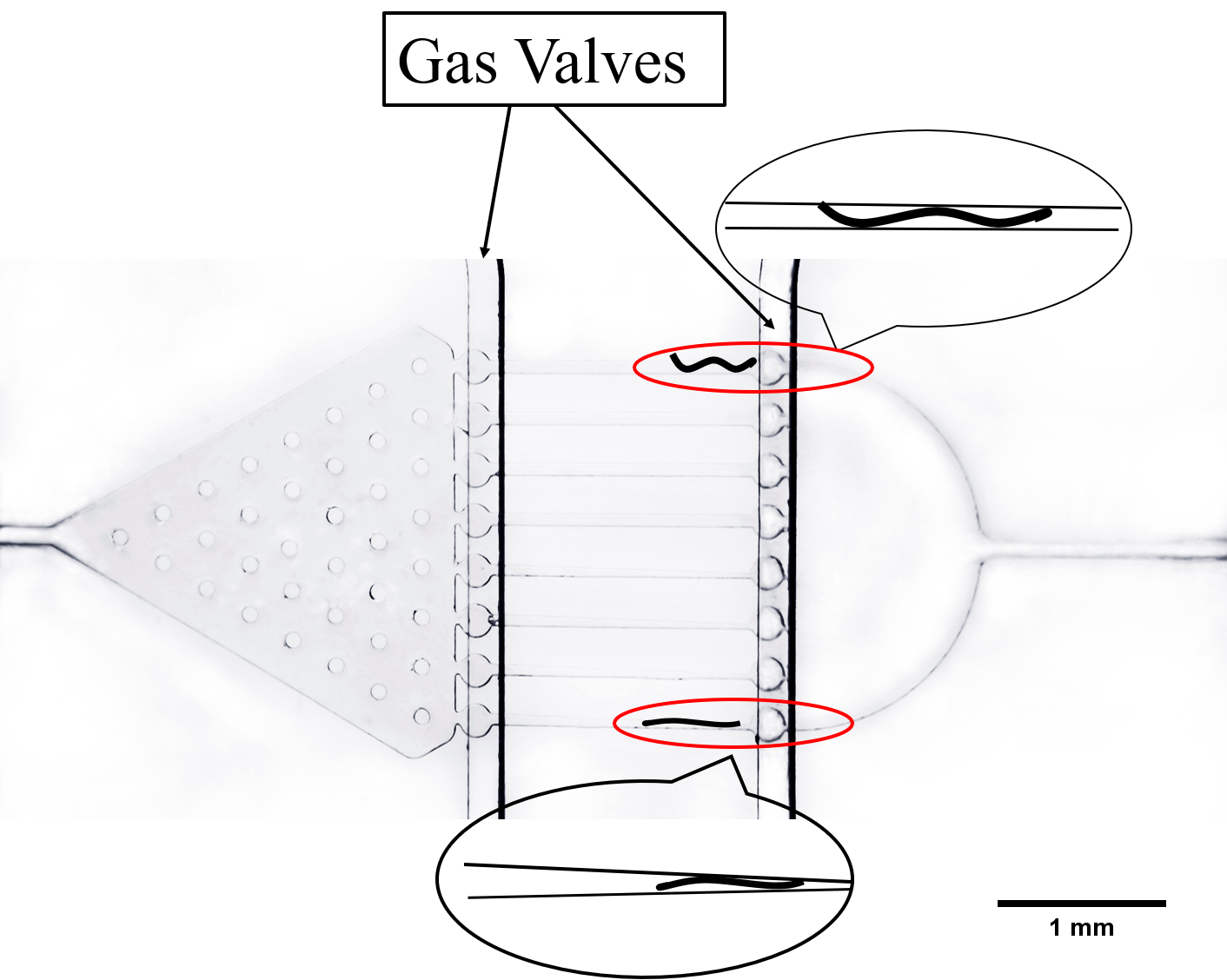
After observing worms’ collective behaviors and proving their olfactory neurons are not affected by exogenous genes, we could study their individual behavioral response and live neuron activity under a light stimulus of a specific wavelength. Traditionally, anesthetics and glues are utilized to immobilize worms. However, worms will be damaged in this condition and it will make it difficult to study the live behavioral response of worms. Thus, we designed two kinds of microfluidic chips to allow high-resolution microscopic imaging on chip without damaging for worms. (Fig. 9)
The first kind of channel is trapping worms in the wedge-shaped channel, called worm clamps. It is utilized to observe the contraction and elongation of their heads and study the neuronal activity by detecting calcium indicator GEM-GECO on fluorescence microscope.
The second kind of channel is compressed and rectangular called parallel channel. Worms can be restricted by turning off gas valves in this compressing channel.
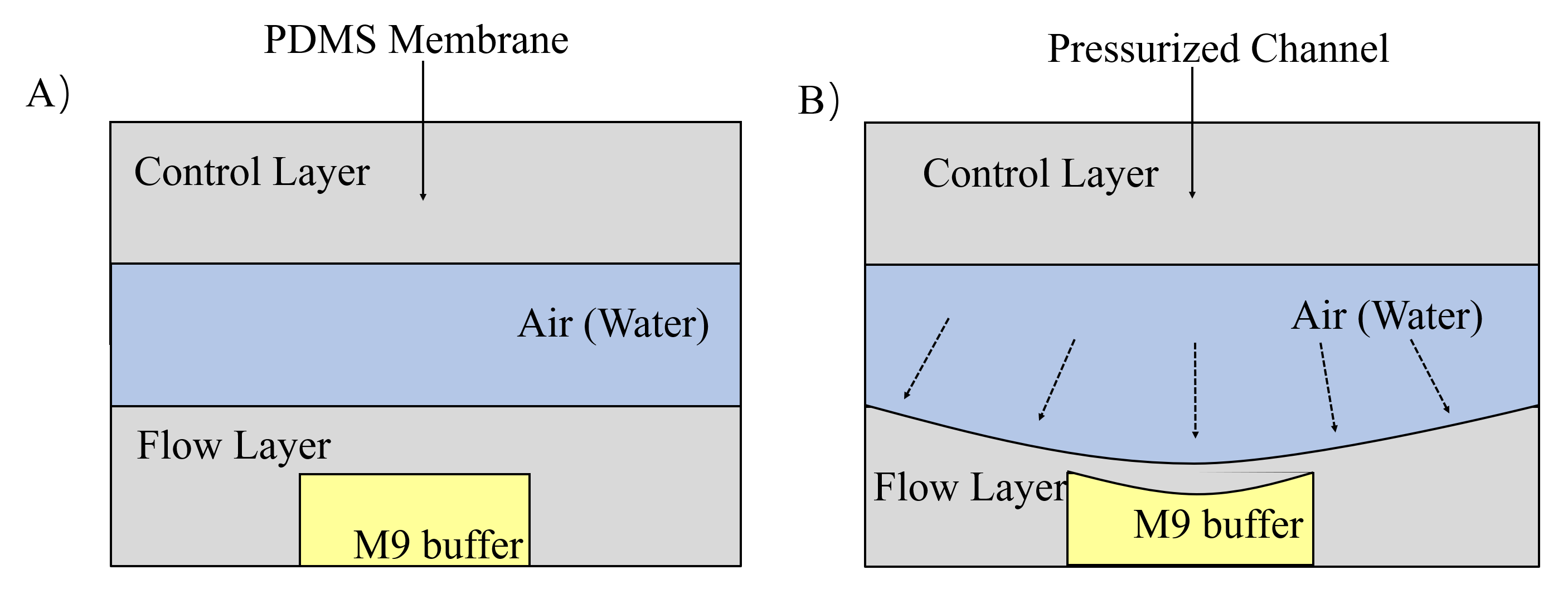
Both of these channels can restrict worms. But in case that they go away from channels, we designed gas valves to block their entry and exit by compressing PDMS (a flexible and easily deformed material) under the pressure made by water or air. The principle of gas valves is as below. (Fig. 10) [3]
Fabrication of Microfluidic Chips
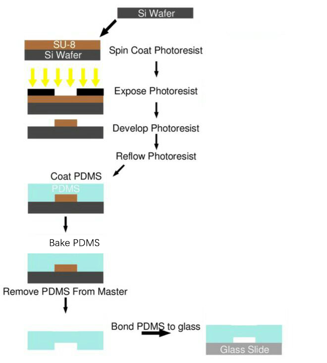
After designing these microfluidics, we need to fabricate them and utilize them. The microfluidic chips used in our project were all produced using this protocol designed by SUSTech_Shenzhen 2016. (Fig. 11) Detailed Protocol
Learn more details Detailed Results
References
- ↑ Albrecht, D.R., and Bargmann, C.I. (2011). High-content behavioral analysis of Caenorhabditis elegans in precise spatiotemporal chemical environments. Nat. Methods 8, 599-605.
- ↑ Bean machine. (2017, October 5). In Wikipedia, The Free Encyclopedia. Retrieved 12:46, October 22, 2017, from https://en.wikipedia.org/w/index.php?title=Bean_machine&oldid=803992086
- ↑ Unger, M.A., Chou, H.P., Thorsen, T., Scherer, A., and Quake, S.R. (2000). Monolithic microfabricated valves and pumps by multilayer soft lithography. Science 288, 113-116.

