Joe McKeown (Talk | contribs) |
Joe McKeown (Talk | contribs) |
||
| Line 178: | Line 178: | ||
<li> | <li> | ||
<div style="border-style: solid; border-color: #162844; border-radius: 25px;"> | <div style="border-style: solid; border-color: #162844; border-radius: 25px;"> | ||
| − | <img width="100%" style="border-style: solid; border-color: #162844; border-radius: 25px;" src=""> | + | <img width="100%" style="border-style: solid; border-color: #162844; border-radius: 25px;" src="//2017.igem.org/wiki/images/f/f9/IGEM-York-Circuitry.jpg"> |
</div> | </div> | ||
</li> | </li> | ||
| Line 188: | Line 188: | ||
<ul style="list-style: none;"> | <ul style="list-style: none;"> | ||
<li><br></li> | <li><br></li> | ||
| + | <li> | ||
| + | <div style="border-style: solid; border-color: #162844; border-radius: 25px;"> | ||
| + | <img width="100%" style="border-style: solid; border-color: #162844; border-radius: 25px;" src="#Circuit Diagram"> | ||
| + | </div> | ||
| + | </li> | ||
| + | </ul> | ||
| + | <center> | ||
| + | </div> | ||
| + | <div class="col-md-3"> | ||
| + | <center> | ||
| + | <ul style="list-style: none;"> | ||
<li> | <li> | ||
<div style="border-style: solid; border-color: #162844; border-radius: 25px;"> | <div style="border-style: solid; border-color: #162844; border-radius: 25px;"> | ||
| Line 202: | Line 213: | ||
<div style="border-style: solid; border-color: #162844; border-radius: 25px;"> | <div style="border-style: solid; border-color: #162844; border-radius: 25px;"> | ||
<img width="100%" style="border-style: solid; border-color: #162844; border-radius: 25px;" src=""> | <img width="100%" style="border-style: solid; border-color: #162844; border-radius: 25px;" src=""> | ||
| + | </div> | ||
| + | </li> | ||
| + | </ul> | ||
| + | <center> | ||
| + | </div> | ||
| + | </div> | ||
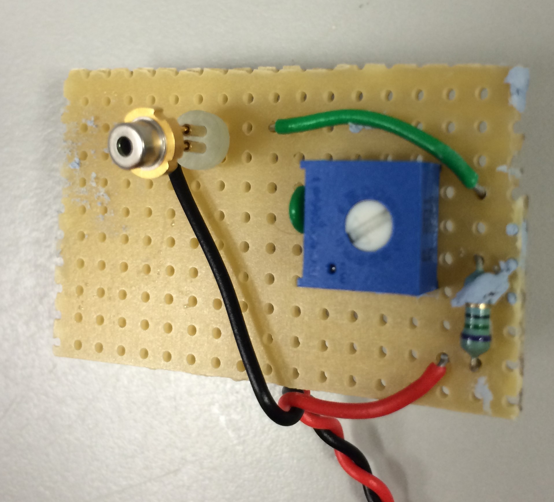
| + | <p style="font-size: 18px; text-align: center;">We used a 635 nm <a style="color: #162844;" href="//www.thorlabs.com/thorproduct.cfm?partnumber=L635P5">laser diode</a> and corresponding <a style="color: #162844;" href="//www.thorlabs.com/thorproduct.cfm?partnumber=S7060R">socket</a> from Thorlabs. Soldering the socket prevents heat damage to the diode itself.</p> | ||
| + | </center> | ||
| + | <!---------------------------------------------------------------------------------------------------------------------------> | ||
| + | <br><hr><br> | ||
| + | <!---------------------------------------------------------------------------------------------------------------------------> | ||
| + | <center> | ||
| + | <p style="text-align: center; font-size: 20px;"><strong>Connect the Laser</strong><br></p> | ||
| + | <div class="row"> | ||
| + | <div class="col-md-3"> | ||
| + | <center> | ||
| + | <ul style="list-style: none;"> | ||
| + | <li> | ||
| + | <div style="border-style: solid; border-color: #162844; border-radius: 25px;"> | ||
| + | <img width="100%" style="border-style: solid; border-color: #162844; border-radius: 25px;" src=""> | ||
| + | </div> | ||
| + | </li> | ||
| + | </ul> | ||
| + | <center> | ||
| + | </div> | ||
| + | <div class="col-md-3"> | ||
| + | <center> | ||
| + | <ul style="list-style: none;"> | ||
| + | <li><br></li> | ||
| + | <li> | ||
| + | <div style="border-style: solid; border-color: #162844; border-radius: 25px;"> | ||
| + | <img width="100%" style="border-style: solid; border-color: #162844; border-radius: 25px;" src="//2017.igem.org/wiki/images/3/3a/IGEM-York-Cable-Feeding.jpg"> | ||
| + | </div> | ||
| + | </li> | ||
| + | </ul> | ||
| + | <center> | ||
| + | </div> | ||
| + | <div class="col-md-3"> | ||
| + | <center> | ||
| + | <ul style="list-style: none;"> | ||
| + | <li> | ||
| + | <div style="border-style: solid; border-color: #162844; border-radius: 25px;"> | ||
| + | <img width="100%" style="border-style: solid; border-color: #162844; border-radius: 25px;" src="//2017.igem.org/wiki/images/e/eb/IGEM-York-Connect-Laser.jpg"> | ||
</div> | </div> | ||
</li> | </li> | ||
Revision as of 03:07, 29 October 2017
Upright DIHM
As outlined on the Description page, we made our microscope out of an aluminium diecast box, a piece of profile extrusion and some plastic blocks. The designs are available via our Downloads page. Once all the parts are acquired, the following assembly process should be used. We have provided step by step instructions, below.
Assembly
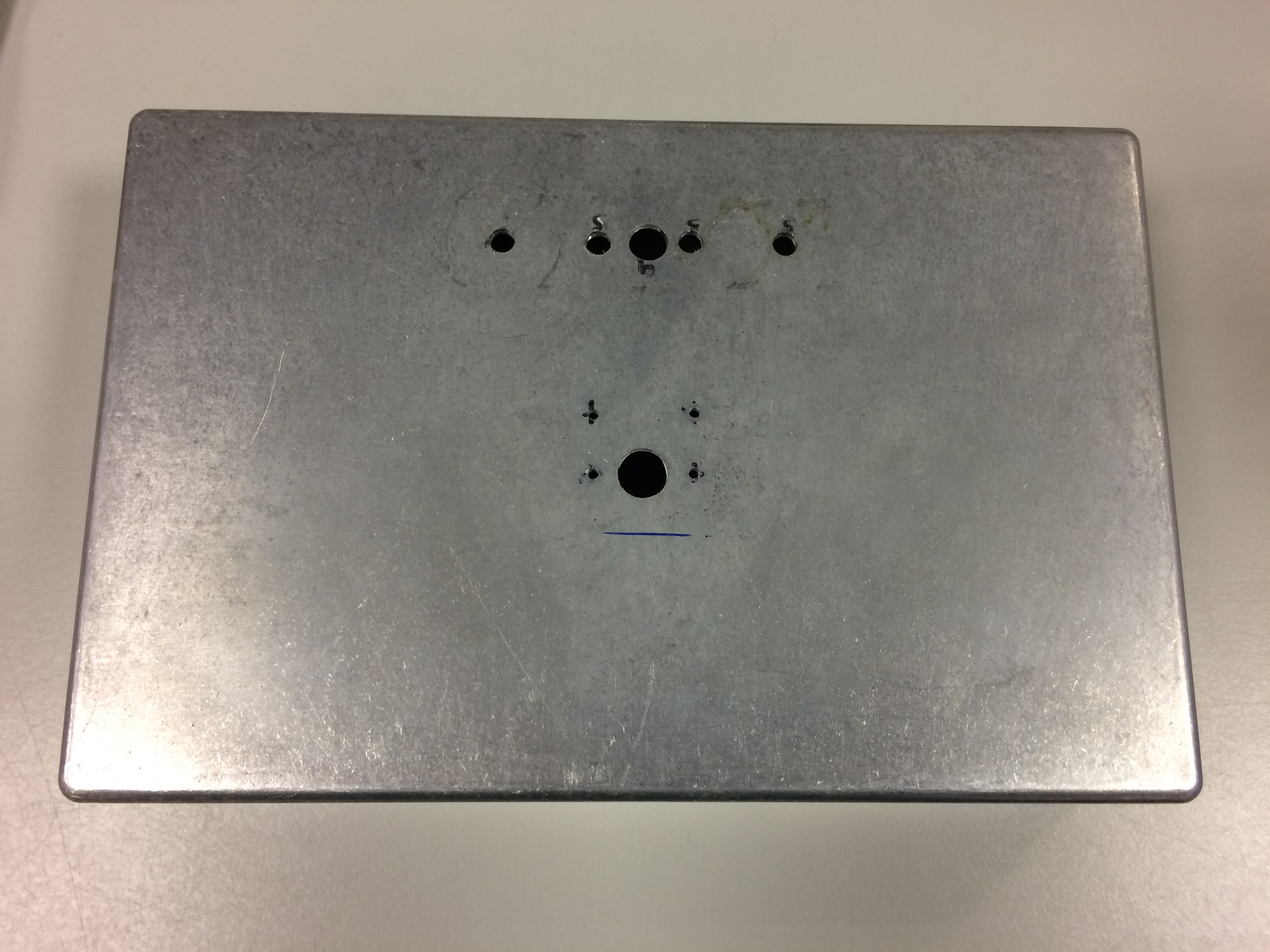
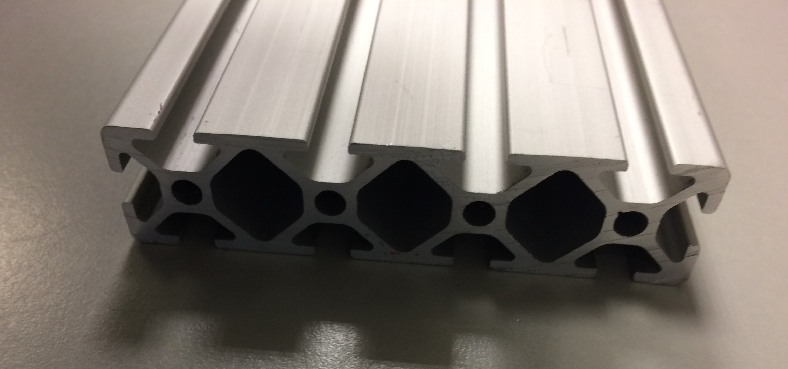
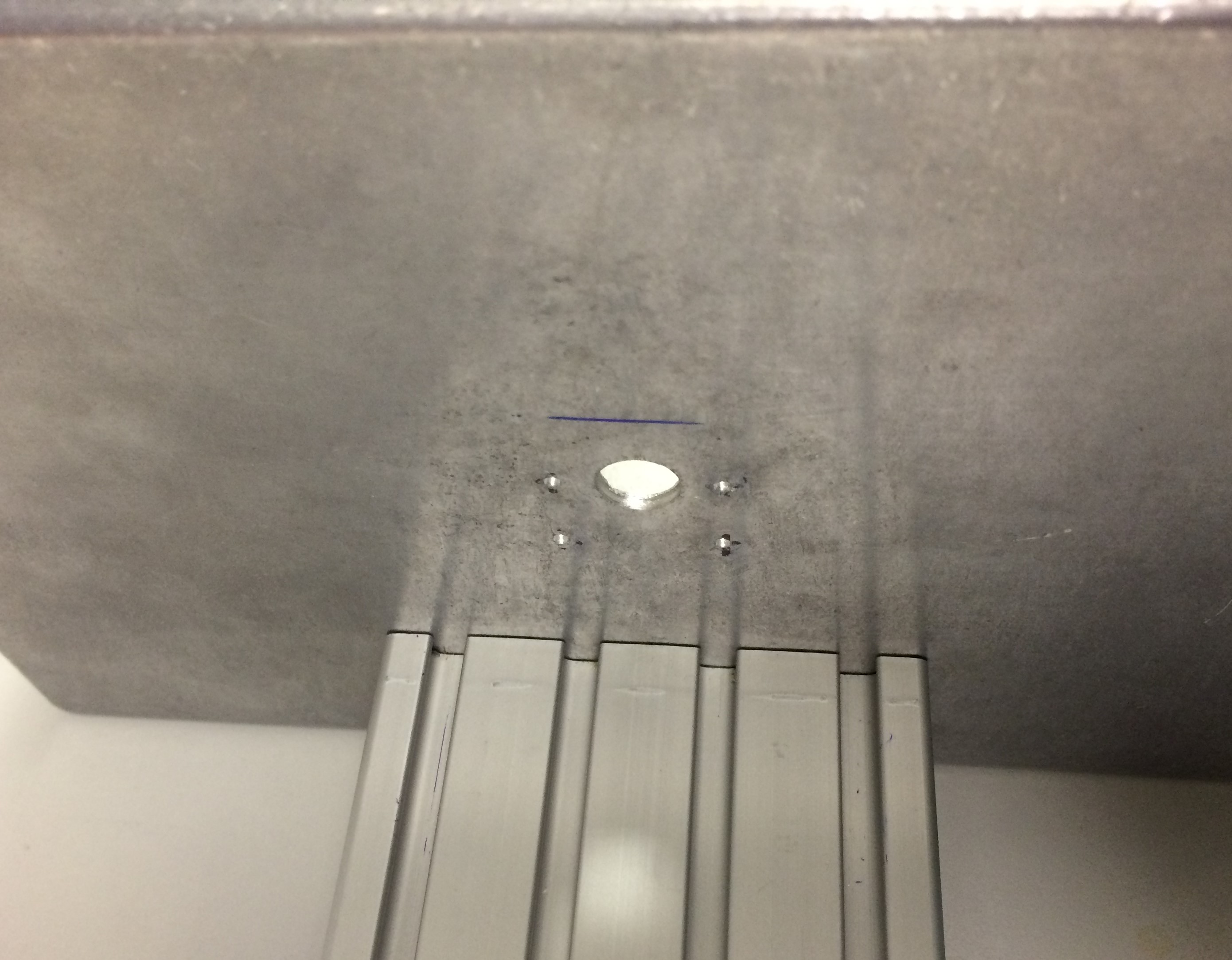
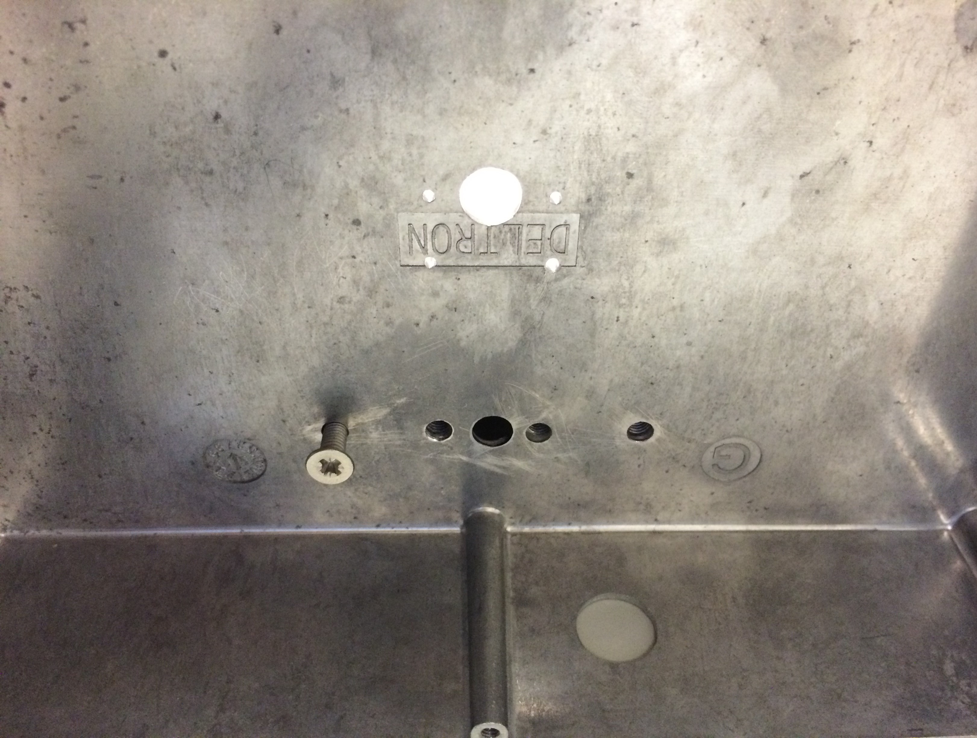
Connect the Base and Profile Extrusion
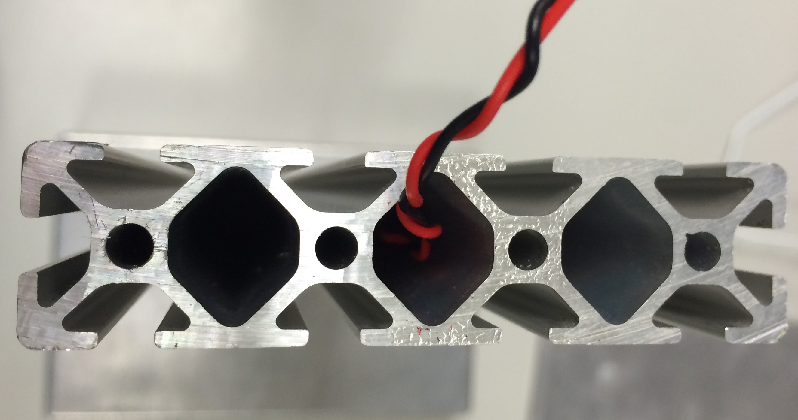
Tap the holes in the profile extrusion so that it can be screwed onto the base as shown.
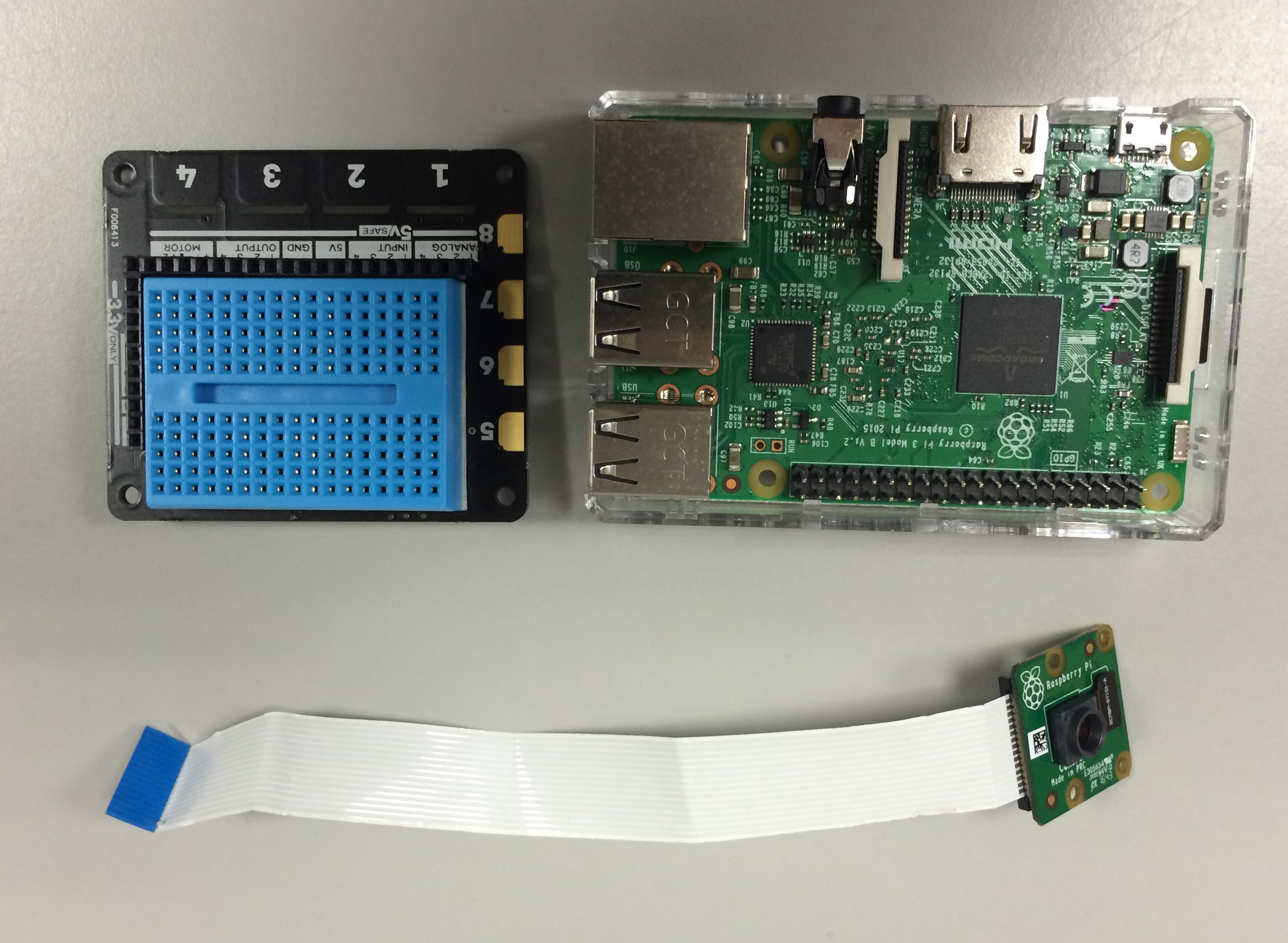
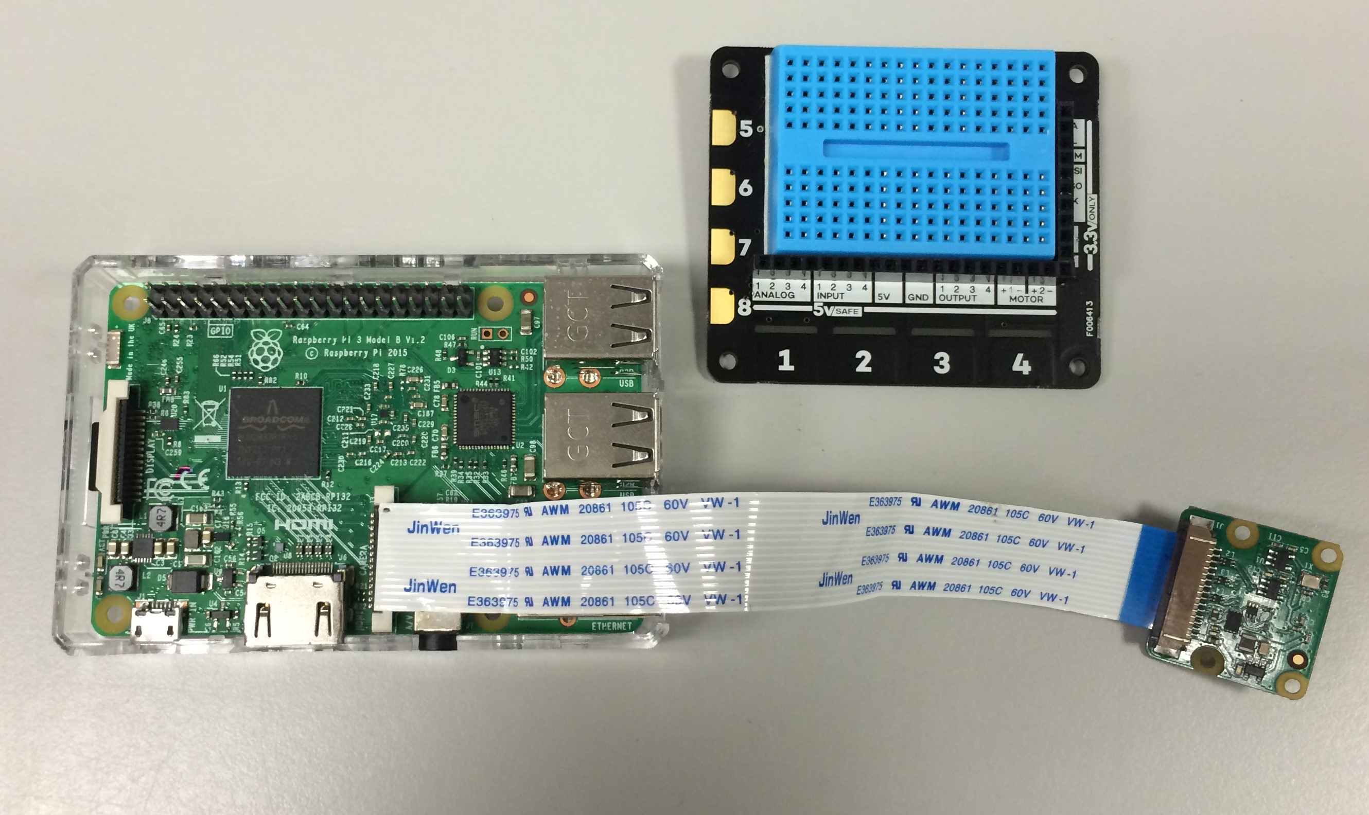
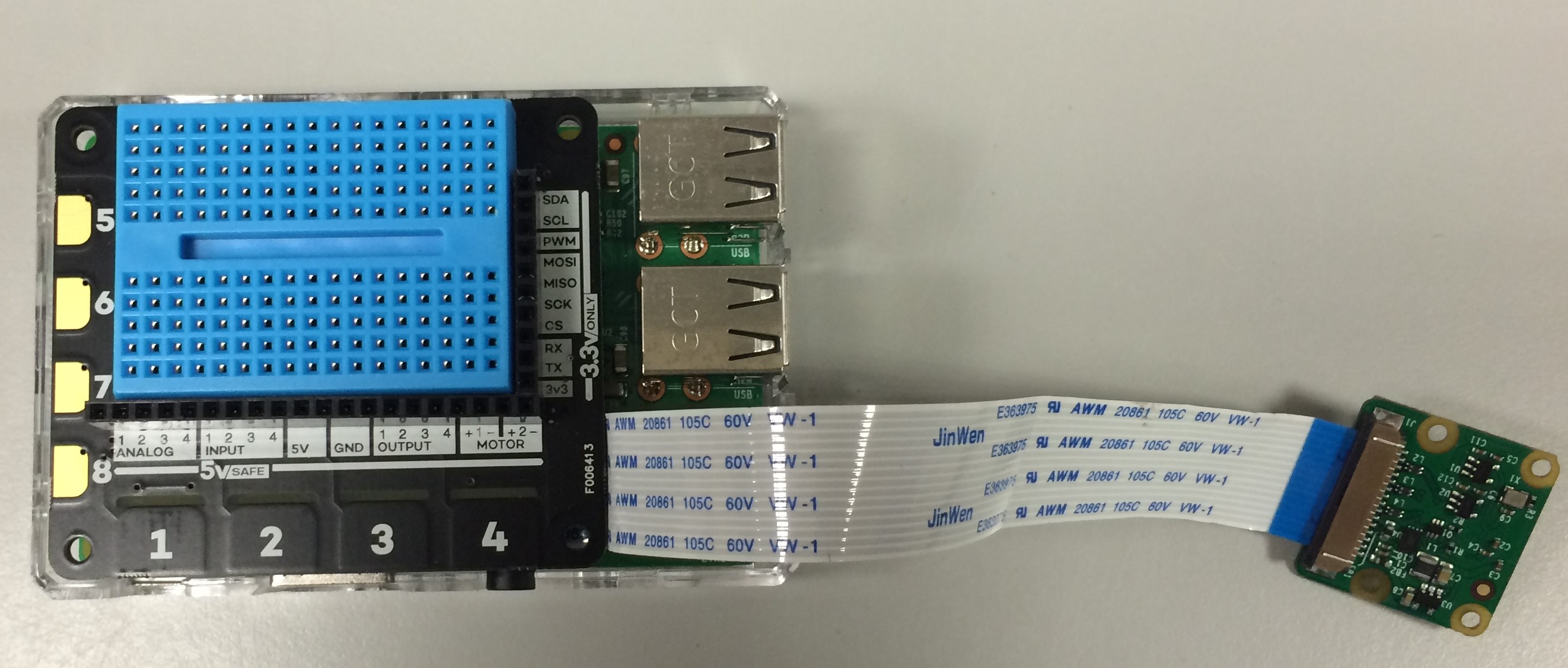
Prepare the Raspberry Pi
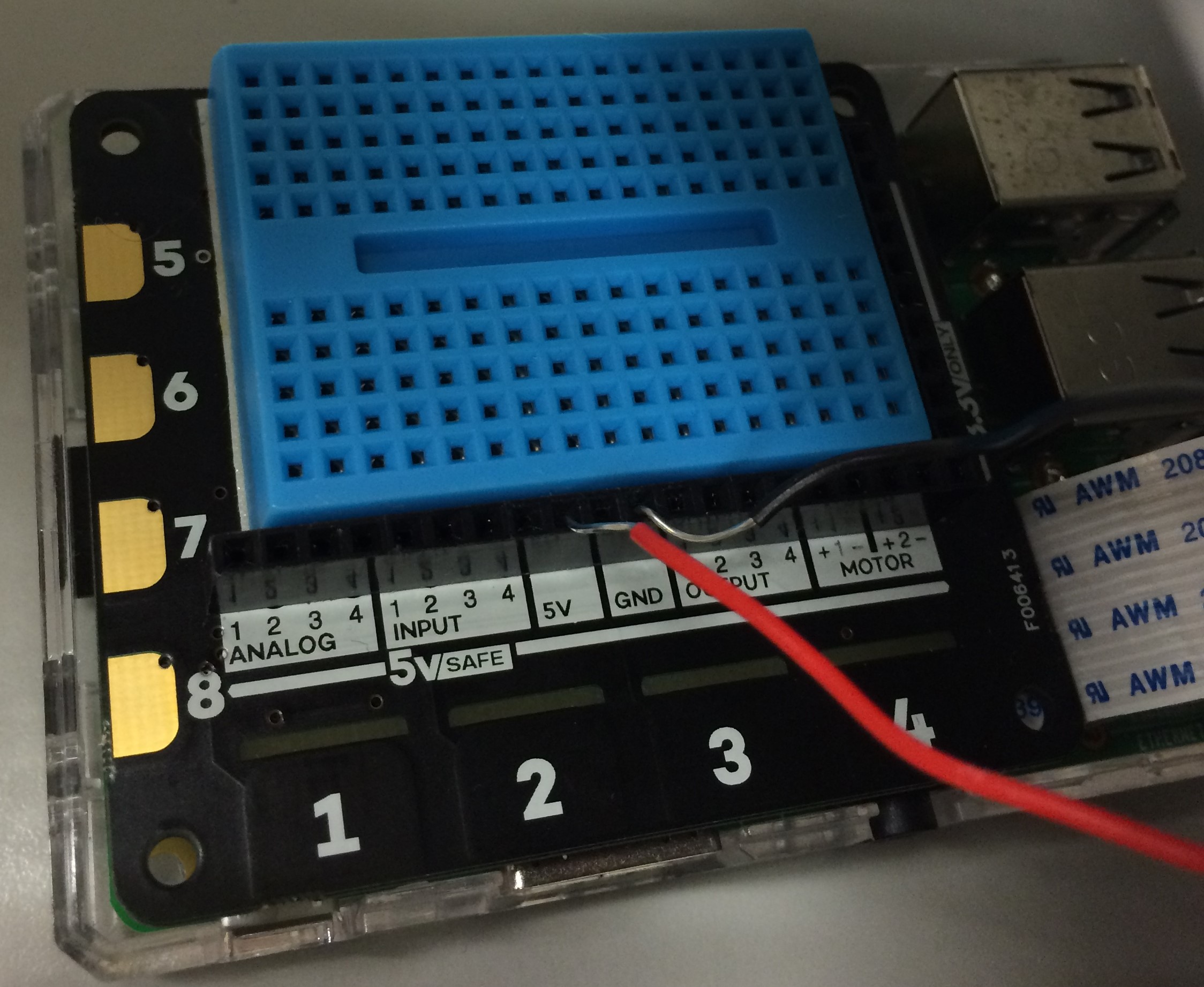
Connect the Explorer hat PRO and Camera Module V2 to the Raspberry Pi 3 as in the images. Note that we removed the lens from the camera.
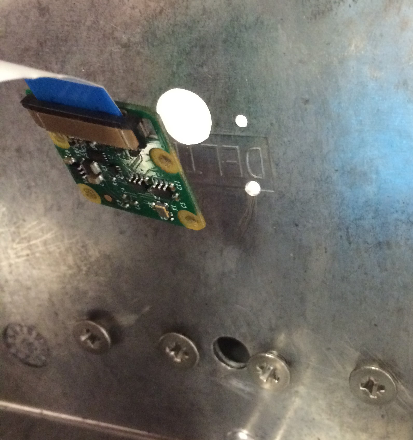
Connect the Raspberry Pi
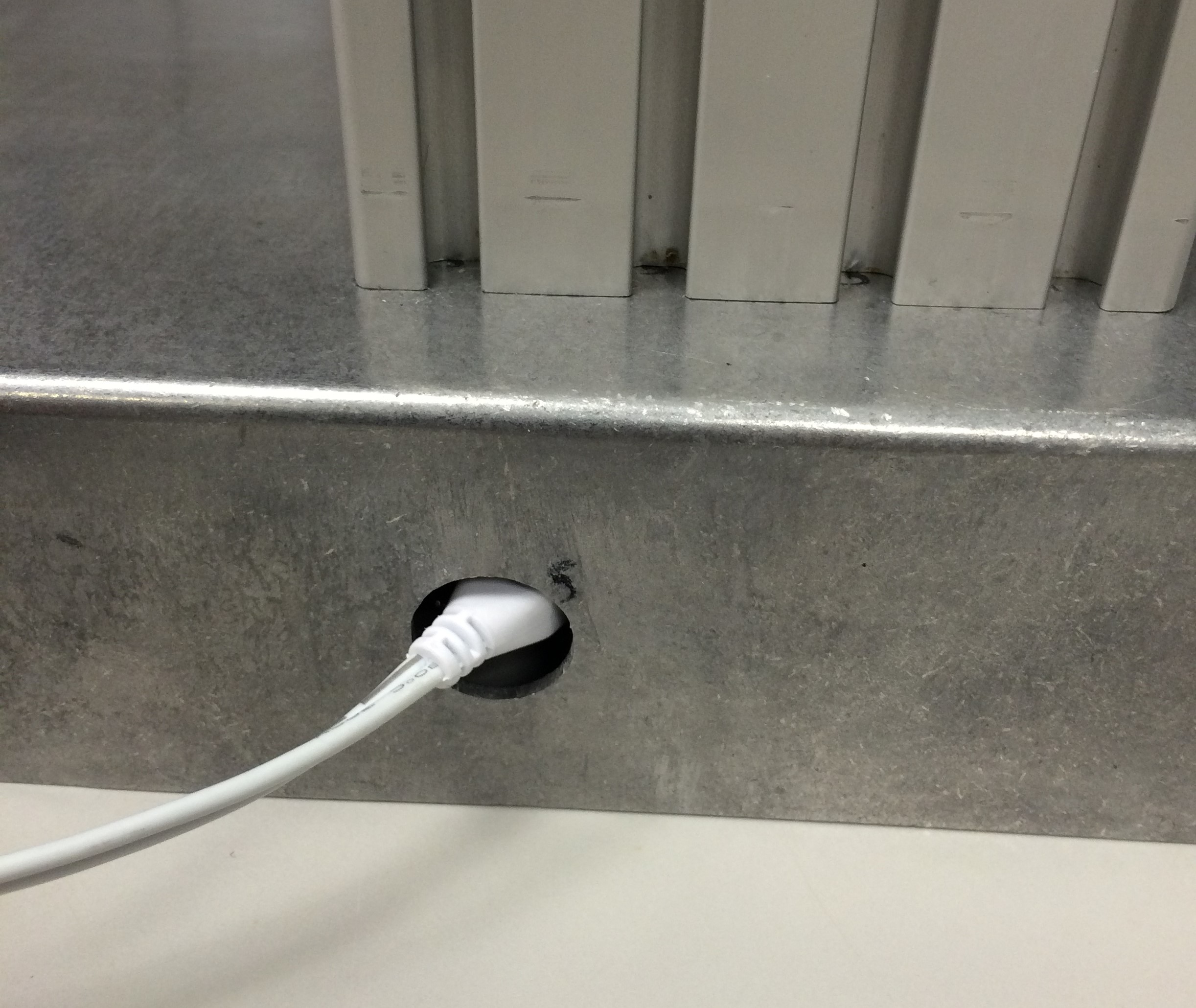
Screw the Camera into the position shown using nylon (non-conductive) screws. Connect the power cable to the Pi through the back of the base. This is also where HDMI/USB connections should be made.
Build the Circuitry
We used a 635 nm laser diode and corresponding socket from Thorlabs. Soldering the socket prevents heat damage to the diode itself.
Connect the Laser
Add the Platforms
Congratulations!
GREEN TITLE
MAIN BODY

