Team:Aachen/Hardware
Achievements

• dosing and pumping with high precision
• wide range of dosing volumes and flow rates
• low-cost & easily to reproduce
• intuitive user interface
• USB remote control
• full documentation, Open Source
• 3 free pumps for next year’s teams
Introduction & Motivation
The initial idea of our hardware project was an automated measurement system, which would measure the response of our yeast cells to different salt concentrations. Droplets of yeast culture mixed with salt solution would circulate in a closed loop of tubing, passing different sensor modules within the loop. More detailed information about this measurement system, which we named Cell Loop, can be found here.
While building concepts for the Cell Loop, our major challenge was finding a liquid handling solution, which can dose precisely and can be controlled via computer. A peristaltic pump would be suitable for dosing and gentle transportation of drops within the loop. Commercial pumps meeting our requirements were available, though costing at least 1300$ per pump ([1],[2],[3]), which is too expensive if we want other teams to pick up on our project. The iGEM-team from Aachen of 2015 already built Do-It-Yourself peristaltic pumps based on a design from thingiverse. [4] Therefore, we firstly tested the suitability of the existing pumps to our Cell Loop setup.
The pumps of the 2015 team were designed for continuous pumping in a bioreactor, where they did a great job, but they were never meant for precision dosing or general use without a bioreactor. For example, only one tubing size fits the peristaltic pump and the diameter was too small for our purpose. Furthermore, the pumps were already partially disassembled, probably when they were separated from the bioreactor and without electrical and programming knowledge they could not be started up

Peristaltic pump build by the iGEM team from Aachen in 2015 [4]
Enabling other teams to reproduce your work is a core aspect of iGEM hardware projects, but the more specialized a device becomes, the lower are the chances that it will be reused or build again. We started to rethink our project: If we built a new pump and the Cell Loop tailored to our needs, it wouldn’t be that useful to other teams. And it was still not guaranteed that we would be able to finish all devices in time for our own project. Moreover, building general applicable devices is even more time consuming, so we decided to focus on a single aspect. Since liquid handling plays a key role in the Cell Loop as well as in many other areas of application, we resolved to build a lasting, well documented peristaltic pump, which can be rebuilt easily and cheaply by upcoming teams in the future. To our best knowledge there was no low-cost solution capable of precision dosing, pumping and being remote-controlled via computer before.
Introducing our peristaltic pump as an open source device, we would like to enable future iGEM teams to pursue our Cell Loop idea further. In addition, we hope to contribute to many other projects involving any kind of liquid handling (e.g. dosing in batch cultures and reactors, continuous bioreactors, automated sampling, microfluidics, lab automation).
TechBricks
Following the idea of the Biobricks philosophy of “Get, Give and Share”, we propose that iGEM teams worldwide can work together to establish a database of electronics and engineering parts called TechBricks. Currently, the iGEM catalog of standard parts only contains a collection of 7 hardware projects from 2013. [5] Why do not make it many more?
A TechBrick should be characterized in that it is easy to reproduce, generally applicable to its task and well documented. TechBricks can play a crucial role in speeding up projects in synthetic biology, saving students and researchers hours of lab work, moreover making some projects possible in the first place. As real building blocks TechBricks should be able to be combined with each other, which raises the question of common standards for hardware and software interfaces.
This task cannot be solved by a single team, as common standards must be accepted by a broad base of users. That's why we would like to invite next year's teams to pick up on the TechBrick idea and get in touch with next year's team from Aachen. Together we could develop common interfaces and standards and incorporate them into future hardware projects.
We want to start by supplying the first TechBrick – by building our very own peristaltic pump designed and optimized by using computer-aided design.
How does it work?

Functional principle of a peristaltic pump [6]
The video offers a view from all sides on our peristaltic pump and it will be shown how the tubing can be inserted into the pump and fastened. Thereafter, it is shown how the bearings on the rotor compress the tubing thus forcing any liquid to be pumped forward. In addition, various configuration options are presented: Three or six bearings can be used and up to two channels can be pumped simultaneously, if another casing part is added.
Demonstration
In the beginning is shown how the pump can be calibrated, additional information about the calibration can be found in our user manual. In the end 100µL water are dosed repeatedly, the results can be read from the scale, demonstrating high precision and reliability of our pump.
Measurements
In order to test the accuracy of the pump, 125 dosing experiments were performed. Various combinations of volume flow and velocity were tested; each combination was tested five times. The data was evaluated considering both trueness and precision. Here, trueness is a measure of the deviation between the measured mean and the set value. Precision determines the variation of the single experiments around their mean.

Representation of the meaning of "Trueness", "Precision" and "Accuracy" using a dartboard.
The investigation of trueness showed a dependency on the flow rate. The calibration performing 30 rotations within 30 seconds with an inner tubing diameter of 0.8 mm led to a flow rate of approx. 3 ml/min. Close to this velocity, the accuracy of the pump is +/- 0.5%. For a significantly faster or lower speed, the average value is about 1% higher or lower as the set value.

Trueness measured as difference between mean and control input over various dosing volumes and flow rates; each data point is the mean of 5 measurements
This leads to the conclusion that a good accuracy can be achieved within the whole bandwidth of flow rates. This accuracy can be further improved by calibrating the system at a comparable flow rate. Parameters in the source code can be accordingly adjusted.

Extract from the source code of our Arduino software – the parameters defining the calibration can be changed without any programming knowledge
Regarding precision, it was shown that the scattering around the mean value increases exponentially with decreasing dosing volume, whereas there is no significant influence by the flow rate. Thereby, dosing is only precise in certain boundaries. In order not exceed a deviation of 2%, a lower border of 50 µL is determined in the specification. However, dosing of smaller quantities is technically possible; but the exponentially increasing error due to variation should be considered.

Precision measured as relative mean deviation over various dosing volumes and flow rates
To test the accuracy of the calibration over long periods of time, an experiment was conducted where three calibrations were performed before and after 12 hours of continuous pumping with a flow rate of 3 mL/min. The results showed a deviation of 0.73 % from 1.639 to 1.651 mL. This shows that our pump is accurate even after long periods of working continuously.
User Testing
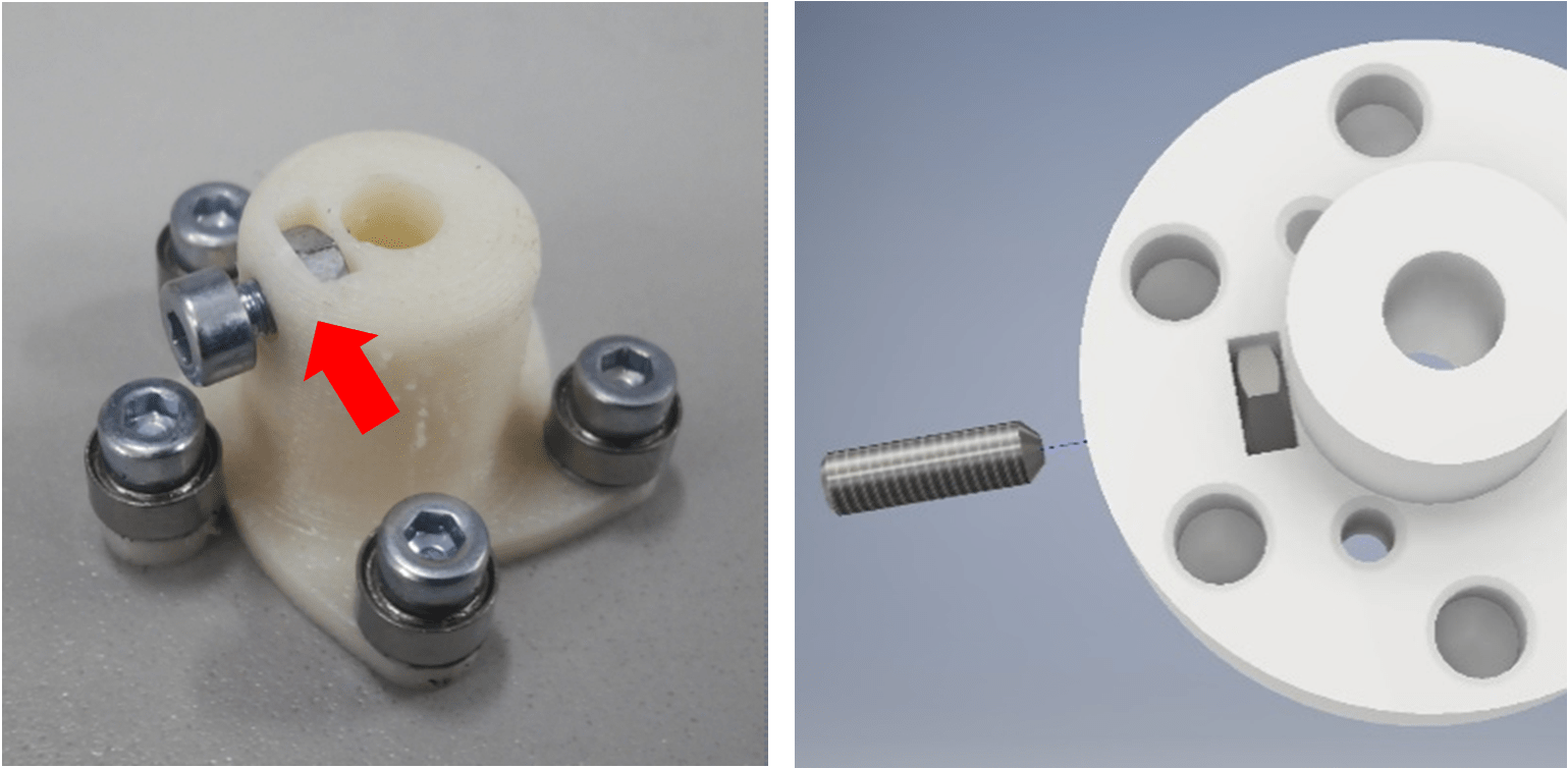
Initially, the pumps built by iGEM Team Aachen 2015 were put into operation and tested, keeping the idea of a universal and accessible liquid handling solution in mind. The necessary tools to build the previous pump comprises both a laser cutter and a 3D printer. To improve the accessibility of our design, necessary tools should be reduced on a minimum. To address this issue, we reduced the tools needed. For the new design, besides a 3D printer, only common tools like a drill, thread cutter, soldering iron and file are needed. Furthermore, the old design only allowed one tube diameter size, reducing the use cases of the pump drastically. The design was improved to allow multiple diameters to enable the usage of the peristaltic pump in multiple applications. A final drawback of the old design was the stability of the combination of a screw and a nut, which fastened the bearing mount to the shaft of the stepper motor. Since only little material was holding the nut in position, the structure behind the nut was breaking easily. Our new design uses a grub screw and more material to support the nut.

The old mechanism (left) [4], which fastened the rotor on the shaft, compared to the new design (right) using a grub screw and more material to support the nut
Summarized, we did a complete redesign from scratch for all parts of our peristaltic pump using the proven combination of the step motor, step motor driver and an Arduino of the 2015 team from Aachen.
In advance of designing a new pump, several potential users like doctoral students and technicians gave us feedback on potential errors and their expectations for a peristaltic pump in general. In this way, we wanted to learn from their experience in order to avoid simple mistakes from the very beginning.
Beveled vents on the backside of the pump
Their feedback has confronted us with several safety issues for a pump used in a wet lab. Considering possible heat developing from the stepping motor, we implemented beveled vents so drops that run down the backside cannot reach the electronics.
In addition, only low voltage of 12V runs the pump and the front interface has a power switch, allowing to stop the pump immediately in case of an emergency. Working with microorganisms, sterilization becomes an important safety aspect, especially if genetically modified organisms are used. Due to the working principle of a peristaltic pump only the tubing has direct contact to the pumped liquid. We used a autoclavable silicone tubing, which allows easy and reliable sterilization (steam 134°C, dry heat 200°C)[7]. Furthermore, all 3D printed parts were made from PETG, a polymer that is compatible to various disinfectants, since it shows good resistance to pure ethanol, propanol and 40% solution of formaldehyde. [8]
After the first pump was built, we had several team members testing the pump, and their feedback has led to further improvements:
Since the rotary knob jumped and could not be precisely adjusted to a value, the software was revised and parameters for the encoder were adapted. Furthermore, the hose slipped slowly through the pump during operation, this issue was fixed by improving the holder. The case slid over the laboratory table, this could be easily fixed by adding some rubber feet.
Eventually, we were able to use the final version of our pump for the experiments we conducted with our cooperation partner GE Power (Link: Integrated human practice) to show the applied design of our project. During this experiment, the pump was used to supply a constant feed of yeast-water mix into a bioreactor. The yeast cells were then filtered from the water using ultrafiltration membranes. (Link: Applied Design)

Experiment for showing the efficiency of the ultrafiltration membranes
Our pump provided a feed of 0.625 litres per hour over the cause of the experiment to keep the volume constant over time. This shows that the pump is not only able to dose volumes very accurately but also can pump at a consistent rate over long periods of time.
Documentation
User Manual
Construction Manual
Results
We built a peristaltic pump as generally applicable liquid handling solution for any project which requires transportation of liquids. Our pump is capable of precise dosing and pumping, providing a wide range of dosing volumes and flow rates to maximize possible applications. Through 125 dosing experiments we were able to demonstrate and quantify the accuracy of our pump. For a tubing with 0,8 mm inner diameter and any flowrate or dosing volume within the specifications we could show an accuracy better than 2% deviation from the set value. Given the results of the measurements, the accuracy can be improved even further if the speed of the calibration is adjusted to the required flow rate.
The pump can be controlled without programming knowledge via the built-in LCD display and a rotary knob. In addition, the pump can be remotely controlled via USB by serial commands. This simple way of communication is compatible with common software and programming languages (MATLAB, LabVIEW, Java, Python, C#, etc.).

Final version of our Open Source Peristaltic Pump
The pump is simple and inexpensive to manufacture, with all the parts totaling less than $100 compared to $1300 for the cheapest comparable commercial solution we could find. Besides a 3D printer, only common tools are needed. Our project is open source in terms of hardware and software. We provide the CAD files for the 3D printed parts, a complete list of all required commercial components and their sources, and the source code used in our pump.
Having designed and tested the peristaltic pump as first open source TechBrick, there is already some major interest in our solution. A research team at the Institute of Applied Microbiology from RWTH Aachen University plans to use our pump in a setup of 4 bioreactors with 3 pumps per reactor. After testing our pumps and building a first prototype, the decision was made to equip the setup with 12 pumps of our type. The pumps will be only operated remotely via computer, so that only the pump head including the electrical system and the software is used. For the larger setup, single housings for each pump and the LCD user interface are not necessary and therefore omitted. In addition, the pump head will be slightly changed to fit in the bioreactor setup. This is a first confirmation that our concept of open source TechBricks is working. We created a universally applicable solution with full open source documentation, enabling other researchers to tailor our TechBrick to their needs.
Specifications

Outlook
We want to make our pump easily available, so that it can support many teams in long term. Therefore, we came up with the following concept. We bought the required parts for three more pumps and we will teach our next year's iGEM team, how to assemble them. As soon as the pumps are working, they will be provided to interested iGEM teams on condition of building their own pump based on our model. In the next year, they can keep their pump, while passing our pump to the next team on the same condition. In this way, more and more pumps will build, supporting iGEM projects around the world and spreading the idea of TechBricks. Furthermore, the teams receiving our pump can immediately start their work and use it as a template for building their own.
If you are interested in getting one of our pumps, please send us an e-mail with a brief description of your project and how you would like to use the pump in it. Also mention which 3D printer is available to you and if you can order all components in your country. Maybe we can help you to order the missing components and send them together with our pump. We will have to pick the three most promising projects, if more than three teams are interested, however we will support anybody who is willing to reproduce our pump. If you have built our pump, please share your experiences and improvements on Thingiverse, GitHub or Instructables.
We expect that by the middle of 2018 there will be 18 functional pumps of our type (3 built by us, 3 built by next year's team and 12 at the Institute of Applied Microbiology from RWTH Aachen University) and we hope for many more!
[1] https://www.coleparmer.com/c/peristaltic-pumps
[2] https://www.fishersci.com/us/en/products/I9C8L80F/peristaltic-pumps.html
[3] http://www.sigmaaldrich.com/labware/labware-products.html?TablePage=9571104
[4] https://2015.igem.org/Team:Aachen/Notebook/Construction_Manuals/Pumps
[5] http://parts.igem.org/Collections/Hardware_Projects
[6] https://en.wikipedia.org/wiki/Peristaltic_pump
[8] http://kmac-plastics.net/data/chemical/petg-chemical.htm#.WfgHMYiDPD4
• User interface
The user interface provides a comprehensive control of the peristaltic pump. It consists of a LCD display, a control knob and a power switch. The control knob can be turned or pushed. Turning the knob allows to select from different menu items, the menu item on the upper line is currently selected. Pushing the knob will activate the selected menu item, indicated by a blinking rectangle. The blinking rectangle implies that the menu item is activated.
Once the menu item is activated, it starts depending on the selected item either an action or allows the change of the corresponding value by turning the knob. For all menu items connected to a numerical value the knob can be held to reset the value to zero or double pushed to increase the value by one-tenth of its maximal value. To set the selected value and deactivate a menu item the knob needs to be pushed a second time.
The power switch will immediately shut down the pump and all its components (Arduino, step motor, step motor driver, LCD), except when the pump is connected via USB. The Arduino and the LCD can be powered by USB, so that the power switch will not affect them.
The pumps menu has 10 items, which are listed and described below:
0|Start
Start pumping, the operation mode is depending on the mode selected at “6) Mode”
1|Volume
Set the dosing volume, is only considered if “Dose” is selected at “6) Mode”
2|V.Unit:
Set the volume unit, options are:
“mL”: mL
“uL”: µL
“rot”: rotations (of the pump)
3|Speed
Set the flow rate, is only considered if “Dose” or “Pump” is selected at “6) Mode”
4|S.Unit:
Set the volume unit, options are:
“mL/min”: mL/min
“uL/min”: µL/min
“rpm”: rotations/min
5|Direction:
Choose pumping direction: “CW” for clockwise rotation, “CCW” for counterclockwise
6|Mode:
Set operation mode:
“Dose”: dose the selected volume (1|Volume) at the selected flow rate (3|Speed) when started
“Pump”: pump continuously at the selected flow rate (3|Speed) when started
“Cal.”: Calibration, pump will perform 30 rotations in 30 seconds when started
7|Cal.
Set calibration volume in mL. For calibration, the pump is run once in calibration mode and the resulting calibration volume which was pumped is measured.
8|Save Sett.
Save all settings to Arduinos EEPROM, values are retained during power off and reloaded, when the power is turned on again
9|USB Ctrl
Activate USB Control: Pump reacts to serial commands sent via USB
• Serial interface – remote control via USB
The serial interface is based on the Arduino’s serial communication interface via USB (Baud 9600, 8 data bits, no parity, one stop bit). Any software or programming language capable of writing data to a serial port can be used to communicate with the pump (MATLAB, LabVIEW, Java, python, C#, etc.). All functions of the pump are accessible by sending the corresponding command to the pump, at the end of each command a new line character '\n' (ASCII 10) is required.
Dose: d(volume in µL),(speed in µL/min),(calibration volume in µL)'\n' e.g.: d1000,2000,1462'\n' (dosing 1mL at 2mL/min, calibration volume = 1.462mL)
Pump: p(speed in µL/min),(calibration volume in µL)'\n' e.g.: p2000,1462'\n' (pump at 2mL/min, calibration volume = 1.462mL)
Calibrate: c'\n'
Stop: x'\n'
The Arduino environment (Arduino IDE) has a built-in serial monitor, which can read and write serial data, therefore serial commands can be tested without any written code.
• Calibration
Performing a proper calibration before using the pump is crucial for precise dosing and pumping. The calibration will tell the pump how much liquid is moved per rotation, so the pump can calculate how many rotations and which speed is needed to meet the set values. To start the calibration, select the Mode “Cal.” and start pumping or send the calibration command via USB. The standard calibration cycle will perform 30 rotations in 30 seconds. The volume of liquid pumped during this cycle (calibration volume) should be measured precisely. Ensure, that the measurement is not affected by drops sticking to the tubing, the weight of the tubing itself or any other interferences. We recommend using a microgram scale for calibration, as you can easily calculate the volume, if density and weight of the pumped amount of liquid is known. Once you measured the calibration volume you can adjust the pump by setting the value of menu item “7|Cal.” or attaching it to your serial commands.
Please note that any change after calibration to the tubing mount or the pressure difference will affect the precision of the pump. Try to perform the calibration always at the same conditions, at which the pump will be used later. If you remove the tubing and install it again in the pump, the calibration value will change up to 10%, since to small differences in positioning and force applied to the screws. Pulling on the tubing will also change the positioning and therefore the calibration value. If the calibration is performed without pressure difference and the pump is later used to pump liquids at another pressure it will affect precision. Remember even a level difference of one meter can create a pressure difference of 0.1 bar, which will have a slight influence on the calibration value, even if the pump can reach a pressure of at least 1.5 bar using the 0.8 mm tubing.