| (16 intermediate revisions by 3 users not shown) | |||
| Line 1: | Line 1: | ||
{{NAWI_Graz:navbar}} | {{NAWI_Graz:navbar}} | ||
<html> | <html> | ||
| + | <div class="jumbotron"> | ||
<div class="section section-heading container"> | <div class="section section-heading container"> | ||
| − | + | <h1>Temperature Interaction Module</h1> | |
</div> | </div> | ||
| − | + | <div class="section-text container"> | |
| + | In this module, tubes carrying the bacterial suspension are coiled between a Peltier-element and a styrofoam block allowing for quick heating of the suspension. | ||
| + | </div> | ||
| + | </div> | ||
| + | <div class="section-sub-text container"> | ||
| + | <img class="section-image" src="https://static.igem.org/mediawiki/2017/a/ad/IM-temp_parts_labelled.png" alt="FIGURE"> | ||
| + | <b>Fig. 1:</b> Assembly of the heat shock element that was used to induce the promoter by heating the silicone tubing to ~40°C for a short period of time. | ||
| + | |||
| − | + | </div> | |
| − | <div class="section- | + | <br> |
| − | <img src="" alt=" | + | <div class="section container"> |
| + | <h2 class="section-sub">Construction</h2> | ||
| + | <div class="section-text container"> | ||
| + | <p> | ||
| + | On top of a ~10x10x10 cm aluminium block thermal compounds was added and a Peltier element sticked to it. The warm side was facing away from the block. The silicone tubing coming from the peristaltic pump that was attached to the main reactor bottle was curled a couple of times and glued to the Peltier element. A hole was drilled into a styrofoam block that approximately had the same lengths as the aluminium block. Inside that hole a temperature sensor (<a href="https://datasheets.maximintegrated.com/en/ds/DS18B20.pdf">DS18B20 digital temperature sensor</a>) was placed and wired to a “Raspberry Pi 3” (RPi). This way it was possible to monitor the “heat shock” process.This block was placed over the tubing and fixed to the aluminium block. To control the Peltier element a relay module was also connected to the same RPi. Electricity was taken from a variable power adapter. | ||
| + | </div> | ||
| + | </p> | ||
| + | |||
| + | <div class="section-image container"> | ||
| + | <img class="section-image" src="https://static.igem.org/mediawiki/2017/4/45/Imt2.png" alt="FIGURE"> | ||
</div> | </div> | ||
| − | + | <div class="section-sub-text container"> | |
| − | + | <b>Fig. 2:</b> Picture of the temperature interaction module on the lab bench.</div> | |
| − | < | + | </div> |
| − | + | <br> | |
| − | + | ||
| − | + | ||
| − | + | ||
| − | + | ||
| − | + | ||
| − | + | ||
<br> | <br> | ||
</html> | </html> | ||
{{NAWI_Graz:footer}} | {{NAWI_Graz:footer}} | ||
Latest revision as of 23:48, 1 November 2017
Temperature Interaction Module
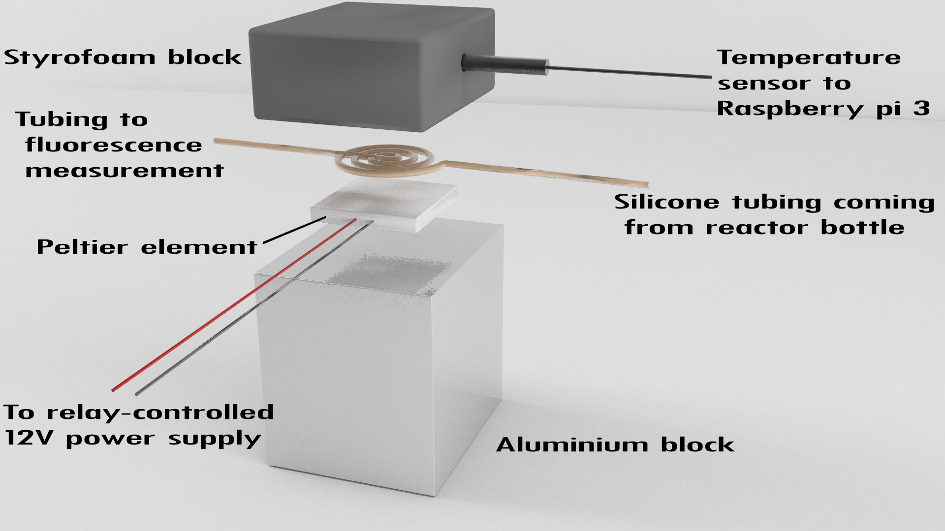
 Fig. 1: Assembly of the heat shock element that was used to induce the promoter by heating the silicone tubing to ~40°C for a short period of time.
Construction
On top of a ~10x10x10 cm aluminium block thermal compounds was added and a Peltier element sticked to it. The warm side was facing away from the block. The silicone tubing coming from the peristaltic pump that was attached to the main reactor bottle was curled a couple of times and glued to the Peltier element. A hole was drilled into a styrofoam block that approximately had the same lengths as the aluminium block. Inside that hole a temperature sensor (DS18B20 digital temperature sensor) was placed and wired to a “Raspberry Pi 3” (RPi). This way it was possible to monitor the “heat shock” process.This block was placed over the tubing and fixed to the aluminium block. To control the Peltier element a relay module was also connected to the same RPi. Electricity was taken from a variable power adapter.


