Design Process
The design process of our biosensor device involved a series of conceptual iterations before finalising on our fourth iteration as previously described. The previous conceptual iterations are described as follows.
Iteration 1
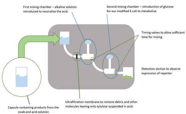
- The surface or area to be tested would be swabbed and then this swab would be mixed with a capsule containing an acidic solution which acted to remove the xylulose from the polysaccharide capsule of any Campylobacter cells present in the swabbed area. It was at this stage that the acid would be heated up which would be done by using the resistance heater electrical circuit that we created.
- The acid mixture would then be entered into the microfluidic device where it would then be driven through the channels by a syringe pump.
- An ultrafiltration membrane, a filter with a pore size so small that only dissolved particles are able to pass through, would stop any debris (such as dirt picked up from swabbing or lysed cells resulting from the heating stage) from passing through and allow only the xylulose and other dissolved substances to continue to the detection area. This would also prevent the larger debris particles potentially blocking the very narrow channels which is a common problem in microfluidics.
- The first mixing chamber enables the introduction of an alkaline solution to neutralise the acid such that the modified E. coli cells that were to be used to detect the xylulose would not be damaged.
- The second mixing chamber would introduce a glucose solution so that the E. coli cells would metabolise this instead of any xylulose present, giving the xylulose molecules a chance to activate our construct.
- The detection area. Here the modified E. coli cells were to be housed and, if xylulose was present, would express a reporter protein such as green fluorescent protein (GFP). A simple light detection circuit would then detect the intensity of light emitted from the cells when they were excited with light of the correct wavelength. This would give an indication of how much GFP had been produced and as such, how much xylulose was present in the initial sample and therefore the level of Campylobacter contamination in the swabbed area.
Iteration 2
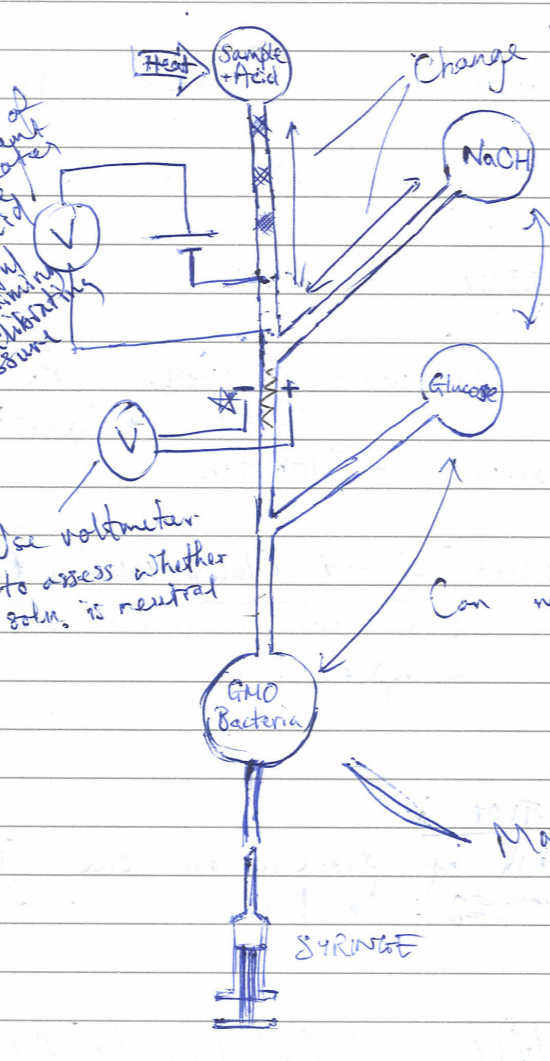
It was observed that the initial solution would have required the use of more than one step of input from the user. Since the goal at first was to complete the process in as well-automated a manner as possible, the device concept was rethought. This time, only one syringe pump was intended to be used for moving solutions through the channels of the microfluidic device. However, this syringe pump would be located at the end of the channel and draw the fluid through. Using this method also meant that the sample could be heated in a pot at the beginning of the process without it seeping through the device unintentionally. This concept is illustrated in the figure on the left.
As can be seen from the diagram above (figure 2), the different fluids in different chambers would have been moved using negative pressure created by drawing the syringe out. After discussing the concept with Melanie Jimenez it was found that there were, unfortunately, drawbacks that indicated that it was not a viable option. These drawbacks are outlined as follows:
- Variations in the viscosities of fluids would cause non-uniform mixing of the samples inside the construct.
- Microfluidics is very temperamental and prone to blockage which is very difficult to correct.
Iteration 3
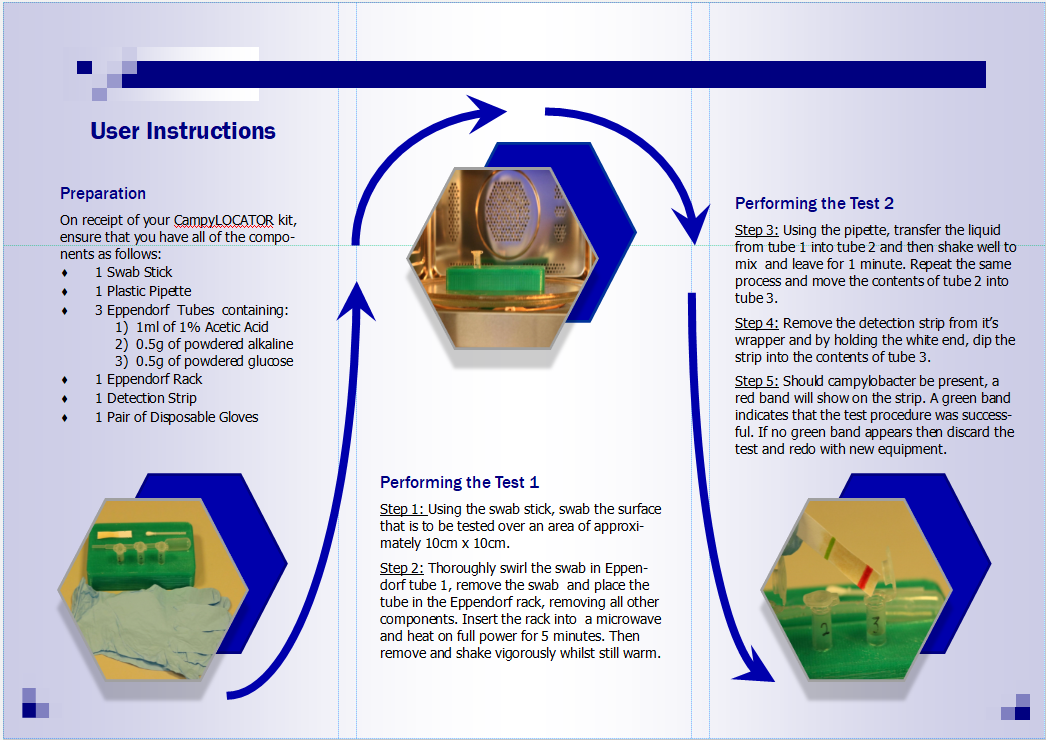
In light of the advice provided by Melanie, we opted to drastically simplify the design of our device. We steered away from using the nanolitre-scale (nL) volumes associated with microfluidics and decided to use a design which utilised larger volumes of liquid which would be much more common to the intended customer and thus easier to use. The device, now a “detection kit”, still included all the stages used in the previous iterations, such as the heating and acid neutralisation steps, however they were deconstructed into a simple and easy to follow layout. To assist the intended user with the operation of the detection kit, a leaflet was made to take the user through the step by step process which is shown in figures 3 and 4 below.
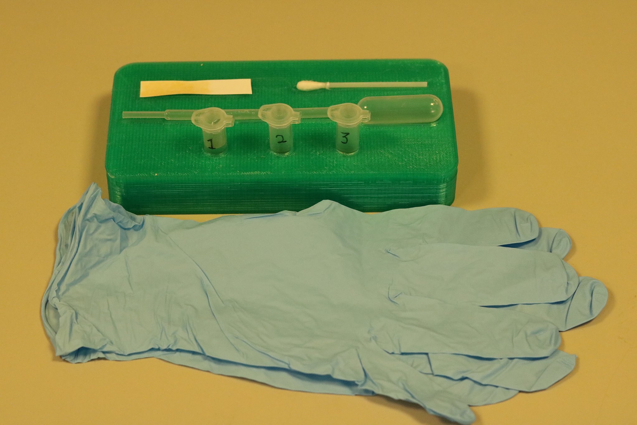
Figure 5, above, shows a close up of the detection kit in its entirety. The green rack that holds all of the components was custom designed using the computer aided design software SOLIDWORKS and then manufactured using 3D printing giving us a product that was perfect for our design.
Ultimately, this design was never completed as shortly after designing and manufacturing the detection kit, we had a discussion with our supervisor Julien Reboud who raised some concerns associated with this type of design over the more automated and contained microfluidic chip. Even though the operation process of the kit is simplified and aimed at a general member of the public, there are still too many possible sources of error that could result in either a false result or no result at all. Additionally, because this design requires the user to transfer the liquids between each tube, there is the potential for the substances spill or come into contact with the user and thus a small chance of causing harm even if the concentrations of the substances used are almost negligible. It was because of these reasons that we moved on to our next iteration of the design.
Iteration 4
The fourth iteration of the device addressed the following issues:
- Exposure of the user to potentially harmful substances.
- Large volumes reduce chances of detection.
- Multiple steps of involvement increases chance of failure.
This iteration was formed through a series of redesigns. Firstly, the construct was formed of around 4 component parts: a fluidic plate using larger, microlitre-scale (µL) volumes instead of the nanolitre-scale volumes suggested in Iteration 2, a 3D-printed pot to receive the sample, a swab, a 3D-printed rubber stopper and a syringe/pipette to deliver acid and the sample.
Overall, the device can be considered as 3 separate parts:
- Fluidic/Processing Plate
- Sample Collection/Delivery Mechanism
- Heating Element
More detail on the final iteration of our device can be found on the respective page.


